Networking and Cisco IOS
Table of Contents
Cisco Network Design Hierarchy 6
Structure: L3 IPv4 Packets and L2 Ethernet Frames 12
TCP: Transmission Control Protocol 19
CDP: Cisco Discovery Protocol 28
LLDP: Link Layer Discovery Protocol 28
L3 (Multiplayer) Switch Operation 30
VLANs: Virtual Local Area Network 32
Protected Port: “PVLAN Edge” 37
DTP: Dynamic Trunking Protocol 39
VTP: VLAN Trunking Protocol 39
802.1D (STP) & 802.1W (RSTP) 43
Port-Channel / EtherChannel 50
IP route vs IP Default-Gateway 55
FHRP: First Hop Redundancy Protocol 55
HSRP: Hot Standby Router Protocol 56
VRRP: Virtual Router Redundancy Protocol 58
GLBP: Gateway Load Balancing Protocol 59
Time Protocols: NTP, SNTP, PTP 62
DHCP: Dynamic Host Configuration Protocol 67
RIP: Routing Information Protocol 74
OSPF: Open Shortest Path First 74
EIGRP: Enhanced Interior Gateway Routing Protocol 82
EIGRP: Configure Bandwidth that EIGRP can use 83
EIGRP: Authentication w/ MD5 83
EIGRP: Create a Keychain & Key 84
EIGRP: Configure EIGRP auth using keychain & Key 84
BGP: Border Gateway Protocol 84
VLAM: VLAN Access Map / VACL 89
NAT : Network Address Translation 92
IP SLA: Service Level Agreement (and tracking) 94
SNMP: Simple Network Management Protocol 95
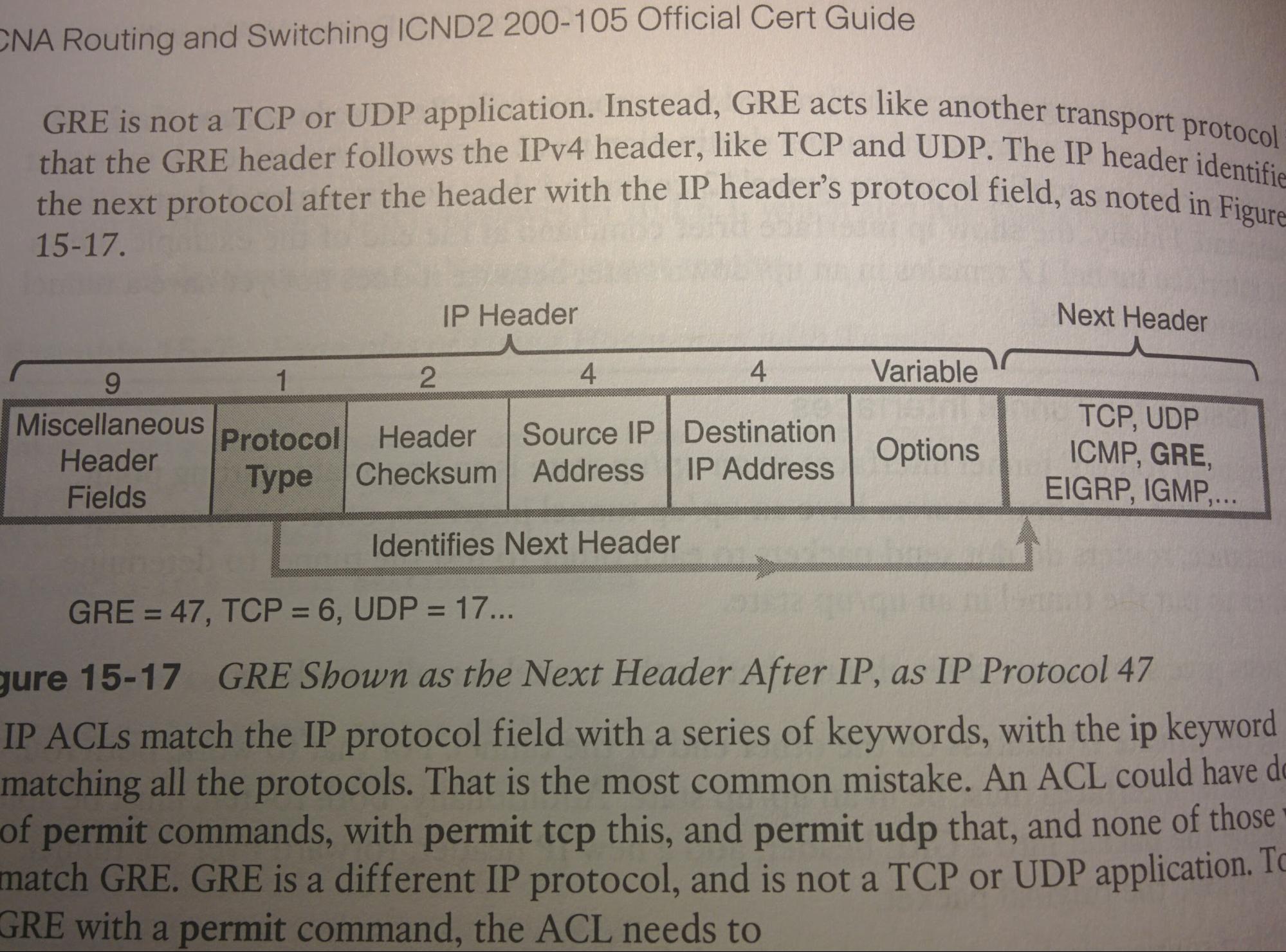
GRE Tunnel: Generic Routing Encapsulation Tunnel 98
WANs: Point-to-point Wide Area Networks 100
PPP: Point-to-Point Protocol 103
PPPoE: Point-to-Point Protocol over Ethernet 107
Private WANs w/ Ethernet & MPLS 110
Carrier Ethernet / “MetroE”: Metro Ethernet 111
MPLS: Multi Protocol Label Switching VPNs 112
Private WANs w/ Internet VPN 113
Multipoint Internet VPNs using DMVPN 116
FlexStack (and FlexStack-Plus) 117
StackWise (and StackWise-Plus) 118
Chassis Aggregation / VSS: Virtual Switching System 119
Supervisor Redundancy Options 121
DAI: Dynamic ARP Inspection 139
SDN: Software Defined Networking 141
Intro
I use this to take notes on networking stuff and Cisco things. It is far from perfect, including many formatting inconsistencies, but is a centralized location I can use to reference information, and I am making it better. I started this in early 2015, and moved it to Google Docs sometime after. Feel free to leave suggestions by editing, adding, or removing as you feel is best.
This whole thing is for educational purposes only. Some pictures were from the sourced books, other from the sourced websites. I don’t own them.
Sources
- The internet.
- https://*.cisco.com/*
- http://ciscopress.com/*
- https://*.netacad.com/*
- http://onfterminal.com/rom-ram-nvram-and-flash-memory-on-cisco-routers/
- http://ptgmedia.pearsoncmg.com/images/*
- http://apprize.info
- http://www.chris-tech.net
- https://www.freeccnaworkbook.com
- https://www.nesevo.com
- https://en.wikipedia.org/*
- School.
- Work.
- Odom, Wendell. CCENT/CCNA ICND1 100-105 official Cert guide. Indianapolis, IN, Cisco Press, 2016.
- Odom, Wendell, and Scott Hogg. CCNA Routing and Switching ICND2 200-105 Official Cert Guide. Indianapolis, IN, Cisco Press, 2017.
- Froom, Richard, and Erum Frahim. Implementing Cisco IP switched networks (SWITCH): foundation learning guide. Indianapolis, IN, Cisco Press, 2015.
- Hucaby, David. CCNP routing and switching SWITCH 300-115: official cert guide. Indianapolis, IN, Cisco Press, 2015.
- Other books.
Key
- Format:
- Bullet-point definition, usually. Most things are listed like definitions and ideas and are bullet pointed, underlined, followed immediately by a colon, some tabs or a newline and then a tab, and then the definition/explanation/summary/whatever. This was decided during creation and is not always used in some (e.g. older) entries.
- The formatting of code / commands will be: a table (typically 1x1 using 1.15 line spacing between commands but 2.0 line spacing for return values) with white colour characters for the actual code, and dark grey 2 colour for comments and the text that prefixes the cmd to indicate the current command mode, a full black background, and Courier New font Arial font. This is to be as similar as possible to using the program “PuTTY” to connect to a device, which should be used because it is free and open source, and works on both GNU/Linux and Windows.
- []: Optional (Although there are many instances of [] where they should really be {} )
- {}: Required
- italics: Emphasis or a string that can be different. (I.e. depends on user input)
- dev: Device
- add: Address (e.g. MAC add)
- cmd: Command
- R: Router
- S: Switch
- L#: Layer # (e.g. L3S = Layer 3 Switch, L4 = OSI layer 4 the Transport layer)
- int: Interface
- Cx: Client / Customer
- Tx: Transmit
- Rx: Receive
- RO: Read-Only (can only read the file, cannot change/edit/delete it)
- RW: Read-Write (can read the file and change/edit/delete it)
- WO: Write-Only (can only be write to the file, can not read it)
Cisco Network Design Hierarchy
- 3-tier Architecture (below)
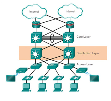
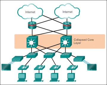
- Collapsed Core (below): Combines core & distribution layers to reduce cost
Layers
- Access Layer:
- Definition: Typically L2 switches (but can be L3) (small/med business: Cisco Catalyst 2960-X series switch; Large Business: Cisco Catalyst 3850-X series switch)
- Purpose: Provide L2 (VLAN) connectivity to (and between) devices. Where end users are connected to the network.
- Low cost per switch port
- High port density (number of switchports on a S)
- Scalable uplinks to higher layers
- High availability
- Ability to converge network services ( that is, data, voice, video)
- Security: Port security, ARP inspection, DHCP snooping, virtual ACLs, and more
- QoS: classification and marking and trust boundaries
- Spanning tree
- PoE (if needed)
- Distribution Layer:
- Definition: Typically a L3S. Cisco (Small/Med business: Catalyst 3850-X Series Switch; Large Business: 4500-X Series Switches)
- Purpose: The uplink from the access-layer.
- IGPs (EIGRP/OSPF)
- Aggregation of multiple access layer switches (both of LANs and WANs)
- High Layer 3 routing throughput for packet handling.
- Security: Security and policy-based connectivity functions: ACLs and filtering
- QoS features
- Connections to core and access layers should be high speed, redundant and scalable (but usually not to other distribution layer devices).
- A boundary for the core layer to use for route summarization / aggregation.
- Boundary for broadcast domains (L3 does not forward L2 broadcasts)
- Core Layer:
- Definition: The network backbone. Simplicity and Efficiency. High speed network devices (Small business/collapsed core: 3850-X Series Switch; Large Business: Cisco Catalyst 6500 or 6800)
- Purpose: Correctly route as many packets as possible as fast as possible. Designed to interconnect multiple campus components (such as distribution modules, service modules, the data center, and the WAN edge). For connectivity between Distribution layer devices.
- IGPs (OSPF/EIGRP) and maybe EGPs (e.g. BGP)
- “Advanced QoS features”
- Reliable: Should redundant and highly available (zero downtime)
- Scaling: By using faster equipment rather than more equipment.
- Avoids: CPU-intensive packet manipulation (caused by security/ACLs, inspection, QoS classification, or other)
Network Design Fundamentals
- Managed Device:
- The ability to put an IP add on a dev, allowing SSH access.
- Campus Network:
- Network of many LANs in many buildings.
- Types of Switches:
- Switch Line:
- Cisco Catalyst Series Switches:
- Designed for Campus Networks; with IOS
- Cisco Nexus Series Switches:
- Designed for Data Centers; with NXOS
- Switch Modularity:
- Fixed:
- WYSIWYG (What you see is what you get) / static / not upgradable.
- Modular:
- Can add modules with different capabilities.
- Switch Mode:
- Store-n-forward:
- Frames is checked for errors (performs a CRC) (typically Cisco Catalyst Switches)
- Cut-through switching:
- Skips the CRC. This lowers latency and assumes that the end dev or high layer protocol will check. (typically Cisco Nexus Switches)
- Broadcast Domain:
- VLAN; Where a broadcast within a certain area will reach.
- Collision Domain:
- Where a potential collision may occur, typically a shared segment (full duplex should prevent collisions).
- Traffic Flow Paths Through a Network Hierarchy:
- Based on where the resource is compared to the end user.
- Local:
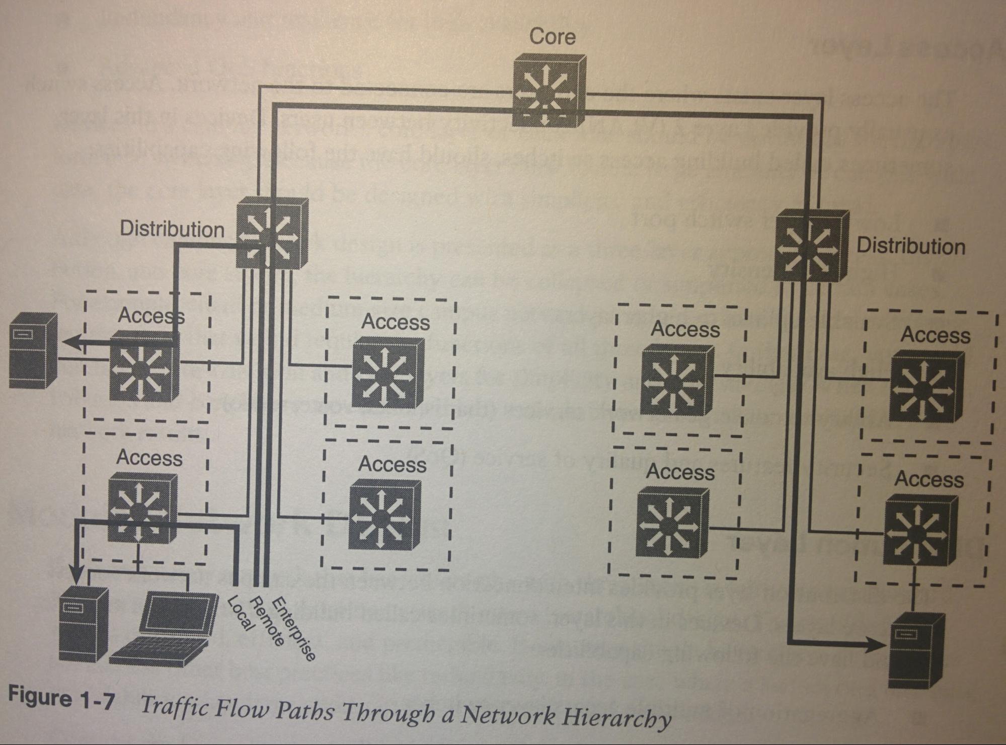
- Crosses layer-access; The service is on the same VLAN/segment/broadcast domain as user. (If this service is needed by users in a different VLAN, then this should be moved up to
- Remote:
- Crosses layer-distribution; Different VLAN/segment/distribution as user. Traffic must cross a distribution switch to access to
- Enterprise:
- Crosses layer-core;
|
Service Type |
Service (server) Location to user |
Extent of Traffic Flow |
|
Local |
Same VLAN(segment) (as user) |
Access |
|
Remote |
Different VLAN(segment) (as user) |
Access > Distribution |
|
Enterprise |
Central to all campus (users) |
Access > Distribution > Core |
- Goals:
- Reduce size of broadcast domains and reduce collisions.
- Don’t use hubs.
- Connect end devices directly into switch ports so they operate in full-duplex mode to prevent collisions all together.
- Design the network around traffic flows rather than a particular type of traffic. Ideally arranged so all end users are an equal distance from a needed resource. i.e. make the resource central to all of the users that need it.
- i.e. if 1 user at the very end of network needs to comm through 2 switches to reach the email server, then all users should have have to comm through 2 switches to reach the email server. The resources should be central to all users that need it.
- Users in two different vlans need to access the same resource, you should not put it in the same VLAN as one of those user’s VLANs but not the other (since it would become a ‘local’ resource to one group but a ‘remote’ resource to another group; bad!). Instead you could put two separate instances of the resource, one in each of the user’s vlans, but then there is no redundancy and two separate failure domains. The best thing to do would to move it up, out of the access layer, and place it separate, in say a seperate vlan, then it would become a ‘remote’ resource to both groups, since the traffic to/from it would cross both the access switches and distribution switch(s).
- Design a network with a predictable behavior in mind to offer low maintenance and high availability. (for when you have to reload / replace a device)
- No Inter-Distribution connections: No connections between distribution layer devices (L3S), to prevent STP loops. All access-layer S’s should connect to each of at least 2 distribution layer S’s (using a FHRP), and those Distribution-layer S’s should each connect to two or more Core-layer devices (not connecting to each other). (idk if one could connect the two distribution layer L3S’s to each other using L3 ports to solve this issue.)
Models: OSI vs TCP/IP
|
OSI |
TCP/IP |
|
Application |
Application |
|
Presentation |
|
|
Session |
|
|
Transport |
Transport |
|
Network |
Internet |
|
Data-Link |
Network Access |
|
Physical |
- OSI Model: Open Systems Interconnection Model. (Older but more detailed, and generally used more)
- Application (>> Application)
- Presentation (>> Application)
- Session (>> Application)
- Transport (>> Transport)
- Network (>> Internet)
- Data-link (>> Network Access)
- Physical (>> Network Access)
- TCP/IP Model: Transmission Control Protocol / Internet Protocol Model. (Newer, but less informative)
- TCP/IP encompasses OSI’s (Application + Presentation + Session) into TCP/IP’s “Application” Layer.
- TCP/IP encompasses OSI’s (Physical + Data-Link) layers into TCP/IP’s “Network Access” layer.
- TCP/IP Model’s Layers:
- Application (Application + Presentation + Session)
- Transport (Transport)
- Internet (Network)
- Network Access (Data-link + Physical)
_____
Merge this below information into the correct locations:
Layers
PDNTSPA
Allows interoperability between vendors
devices only need to be aware of their own layer
layer7webserver does not care if I used fiber or wireless to reach it
layer2Switch does not care what website I am on
UPPER: Servicing and dealing with Application
LOWER: Focus on end-to-end delivery (how through the network) FOCUS ON THIS
7 Application UPPER Host
6 Presentation UPPER Host
5 Session UPPER Host
4 Transport LOW Host Segments
3 Network LOW Media Packets
2 Data Link LOW Media Frames
1 Physical LOW Media Bits
7 Application UPPER
Provides Network services to the end host's Application
E.G. HTML, Email, FTP, Telnet
Telnet: Remote programming of router without being physically there.
SSH: ^ but encrypted
6 Presentation UPPER
Programming language HTML, Java, C, Python, etc
Deals with actual encoding of data. Ensures that data can be understood between two end hosts.
E.G. ASCII character encoding
how JPEG works vs PNG
turn image to JPEG e.g.
5 Session UPPER
Manage session between two end hosts
How end-hosts figure out who they are talking to.
4 Transport LOWER
Look at stuff and say "is this TCP Session or UDP session?""What is the protocol?"
TCP and UDP
99% of applications use one of these two protocols
Most are TCP
Breaks up data between sender/receiver to send (data segmentation)
Takes data from UPPER layers (Application,Presentation,Session) and breaks it up (data segmentation) in order to actually send it.
Use to establish End-To-End-connectivity
"Did you actually receive ma data?"
3 Network LOWER
"Is this my IP that the packet is destined for?"
PATH SELECTION
Layer 3 IP Routers (most routers)
Defines Logical Addressing (IPv4,IPv6 addressing)
2 Data Link LOWER
layer 2 Ethernet switch
Bridges,switches,Wireless Access Points (WPA), ethernet,frame relay, PPP(Point to Point Protocol)
^turns into electrical signal or optical signal
Physical addressing comes in here (MAC address(MediaAcessControl Address))
ethernet
ethernet uses physical/hardware address to communicate
uses (MAC)Media Access Control address to communicate
who can send data when(CSMA/CD)
typically has error detection
1 Physical LOWER
repeaters and hubs(obsolete devices?)
Copper or fiber or wireless(media is air or radio frequencies between them)
electrical functions
physical connectors
cable distances
Structure: L3 IPv4 Packets and L2 Ethernet Frames
Encapsulation Order
Data is encapsulated into a L4 TCP Segment, is encapsulated into a L3 IPv4 packet, is encapsulated into a L2 Ethernet frame, is converted into electrical binary signals and transmitted across a wire.
Once received, the same operation is done in reverse.
Application |WWW|
Presentation
Session
Transport |TCP|WWW|
Network |IPv6|TCP|WWW|
Data Link |B0-5F-56-E0-66-01|IPv6|TCP|WWW|
Physical |011001010111010001101000...
these are just headers, also are trailers, so everything is samiched by what is below it
________________________________________
PDU-Protocol Data Units (Lower Layers)
Datagram: Generic term for any single unit of a layer.
Transport Layer4- Segments
Network Layer3- Packets (aka internet layer3)
Data Link Layer2- Frames
Physical Layer1- Bits
Transport Layer4- Segments (TCP Segments, UDP segments)
Network Layer3- Packets (network packets)
Data Link Layer2- Frames (Ethernet Frames, frame relay frames, PPP frames)
Physical Layer1- Bits (electrical signals, frequencies, how soon electrical signals, or light or frequencies of light, optical wavelengths)
___
Encapsulation and Decapsulation Process
Cheese in sandwich in plastic casing in package in box in pallet in truck.
WHEN TWO ADJACENT LAYERS TALK TO EACH OTHER
when touching layers talk
Layer1 asks Layer2 to send traffic upstairs
TCP at layer4 asks Layer3 (IP) to send traffic to this destination 176.153.7.xx
PDU- what data looks like at layerX
ENCAPSULATION
Sender to receiver Application Layer(1), then add formatting as move down towards Layer1 then can send data over the link (Copper,Fiber,wireless whatever)
Process of adding formatting data on the sending host to create a (PDU)Protocol Data Unit
DECAPSULATION
Process of removing data formating on the receiving host to expose a PDU.
removing formatting from lower layers as we move up towards Application Layer1
Ethernet switch receives physical bits from layer1 wire, takes that framing off, look at Layer2 information like (MAC)Media Access Control Address and figure out what to do with it (which ed host to send to). Once packet(s)get to end-host, end-host will look at layer3 information and say "is this my IP the Packet is destined for?" k "What is transport protocol?TCP Session or UDP Session?" k passes it upstairs to Presentation layer2 "k this is JPEG" tell your Layer1 application(WebbrowserFirefox or app like LoL) to make it appear as a picture."
L3 IPv4 Packet Header
L2 Ethernet Frame
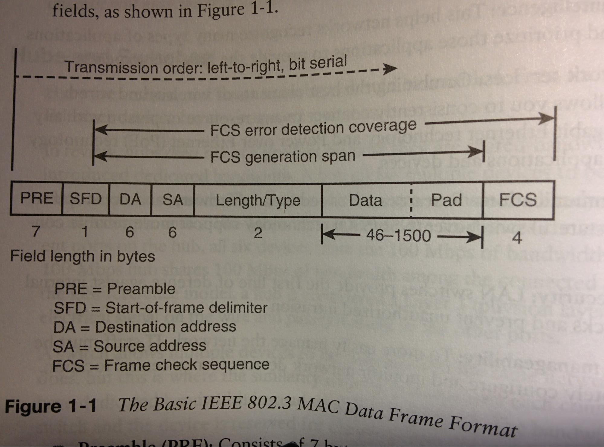
- (PRE) Preamble:
- (7 bytes) Alternating pattern of 1s and 0s (i.e. 101010101…) that tells recipient that a frame is incoming, and helps synchronize for arrival.
- (SFD) Start-of-Frame Delimiter:
- (1 byte) Also an alternating pattern of 1s and 0s (i.e. 10101...), but ends with 2 consecutive ‘1’s (“10101011”). This signals that the next bit is the start of the DA.
- (DA) Destination address:
- (6 bytes) Identifies what station(s) are to receive the frame.
- Significant bits: First 2 bits of DA are special/significant.
- Bit #1 (Address bit): 0 = individual address (e.g. unicast). 1 = group address (e.g. multicast).
- Bit #2 (Administration bit): 0 = globally administered DA. 1 = locally administered DA
- Everything after these in the DA field is the unique MAC address identifying the station(s).
- (SA) Source Address:
- (6 bytes) Mac address of the individual Txing station. (always an individual address, never a group address, as such first bit always 0)
- Length/Type (TLV):
- (2 bytes) If Length/type field value ≤ 1500, then the length/type field value is = the # of data field LLC bytes. If the length/type field value > 1536, the frame is an optional type frame, and the length/type field value identifies the particular type of (optional) frame.
- Data:
- (46-1500 bytes) If data is less than 46 bytes, a ‘pad’/’filler’ is added to make it 46 bytes. Current gen Cisco Catalyst S’s support jumbo frames up to 9000 bytes.
- (FCS) Frame Check Sequence:
- (4 bytes) Is the (32-bit) cyclical redundancy check (CRC) value generated using the DA, SA, Length/type, and Data fields. Used to detect errors of those fields during transit.
IP: Internet Protocol
IPv4
Classful
(~1995 and prior)(OLD)
|
Class |
Private IP Range |
For... |
Bits for Networks |
Bits for Hosts-per-Network |
|
A |
0.0.0.0 - 127.255.255.255 |
(Large Organizations) |
8 |
24 |
|
B |
128.0.0.0 - 191.255.255.255 |
Medium Organizations |
16 |
16 |
|
C |
192.0.0.0 - 223.255.255.255 |
Small Groups |
24 |
8 |
|
D |
224.0.0.0 - 239.255.255.255 |
Used Only Sparingly |
32 |
0 |
|
E |
240.0.0.0 - 255.255.255.255 |
Experimental. Don't use at all |
|
|
Classless
(~1995 and after)(NEW) has Subnet Mask
VLSM (Variable Length Subnet Mask). The subnet mask will even between ip addresses in the same ‘classful class’, e.g. 10.0.255.254/16 and 10.1.0.1/24.
Example
Base10 (decimal)
210.88.239.22
255.255.240.0
Base2 (Binary)
11010010.01011000.11101111.00010110
11111111.11111111.11110000.00000000
Example 2:
192.168.1.1/8
10.0.0.1/16
172.16.1.1/24
These do not fallow the ‘classful’ rules, but rather have non-standard subnet masks from what the address range (e.g. Class C, Class A, & Class B respectively) would typically have had if it was classful.
- IPv4 Private Addresses:
- 10.0.0.0/8 ; 172.16.0.0/16 ; 192.168.0.0/24;. Non-Publicly-Routable, only privately routable (i.e. ISPs drop/filter packets to/from these adds).
- IPv4 Link-Local Addresses:
- “APIPA/Automatic Private IP Addressing”;169.254.0.0/16 ;. Automatically used if a device is unable to lease an IPv4 addresses from a DHCP server.
IPv6
Nibble: AF83
Byte: 84B6.C751
Hextet: 846D.187D.8A63.3597
Interface Identifier = new Host portion of layer 4 networking.
Now there is only the host portion of an IPv6 Address, and an Interface Identifier.
4x as long as IPv4 address
IPv6: 128 bits long = 32 nibbles = 8 hextets
1 HEX SYMBOL IS == TO 4 BITS (BINARY DIGITS)!
1 HEX SYMBOL REPS 4 BITS (BINARY DIGITS)!
Bases
|
Hex |
Binary |
Decimal |
Hex |
|
Base-15 |
Base-2 |
Base-10 |
Base-15 |
|
0 |
0000 |
0 |
0 |
|
1 |
0001 |
1 |
1 |
|
2 |
0010 |
2 |
2 |
|
3 |
0011 |
3 |
3 |
|
4 |
0100 |
4 |
4 |
|
5 |
0101 |
5 |
5 |
|
6 |
0110 |
6 |
6 |
|
7 |
0111 |
7 |
7 |
|
8 |
1000 |
8 |
8 |
|
9 |
1001 |
9 |
9 |
|
A |
1010 |
10 |
A |
|
B |
1011 |
11 |
B |
|
C |
1100 |
12 |
C |
|
D |
1101 |
13 |
D |
|
E |
1110 |
14 |
E |
|
F |
1111 |
15 |
F |
3 types of address'
Unicast
Multicast
Anycast
Unicast
Device to device
Multicast
device to DEVICES
e.g. ARP
Anycast
Loopback
::1 /128 (Hex shortened)
0000:0000:0000:0000:0000:0000:0000:0001 /128 (Hex Long)
(Bin)
00000000.00000000.00000000.00000000.
00000000.00000000.00000000.00000000.
00000000.00000000.00000000.00000000.
00000000.00000000.00000000.00000001
Currently no NAT in IPv6
NAt used to give some privacy from those we send packets back and forth to from being able to see how our private network is laid out.
Router Advertisement (RA)
Router send info to host (using their link local address) telling what network portion of IPv6 address we are using(Global/public unicast network prefix). Tells how it should create its Interface Identifier (host portion) of ip address. Tells how it can get IP address,
Stateful DHCP address acquiring = admin configures everything (scope of IntIDs) and has database of who has what()similar to how we do it today,).
Stateless DHCP = automatically let device determine IntID info, but DHCP server tells what it should use for DNS server and WIN server and that kind of info. DHCP server does NOT record who has what address. Modified-EUI-64 or Privacy (Random)
SLACC
Modified EUI-64 (Linux, Mac, Cisco all use this)
For Interface Identifier portion of IPv6 Address, we take MAC address, split it in half, put FF:FE in the middle of it, then take the first 2 bits of hex (first two characters) translate that to binary, and invert the 7th bit. Then convert back to hex and BOOM you have Interface Identifier portion and now your own IPv6 address.
- IPv6 Unique Local Addresses:
- “IPv6 Private Addresses”; FC00::/7 (which also includes FD00::/7 which is designed for 48-bit prefixes) (originally FEC0::/10 but this was deprecated in 2004 and replaced with FC00::/7 in 2005). Non-Publicly-Routable, only privately routable (i.e. ISPs drop/filter packets to/from these adds).
- IPv6 Link-Local Addresses:
- “IPv6 APIPA Addresses”; FE80::/64 These should only be be used for comms between devices within the same broadcast domain (Rs should drop/filter). Non-Publicly-Routable (ISPs drop/filter packets to/from these adds). Link-Local addresses are required for NDP (IPv6 Neighbor Discovery Protocol). These are typically automatically generated by the OS.
- NDP:
- “Neighbor Discovery Protocol”; Used for gathering info such as gateways and DNS servers. See https://en.wikipedia.org/wiki/Neighbor_Discovery_Protocol
So take mac address of NIC
CB-30-9F-00-0C-29
Split in half (switch - to :)
CB-30-9F 00-0C-29
put FF:FE in the middle
CB30:9FFF:FE00:0C29
translate first 2 hex bits to Binary
CB ---> 1101 1100
invert 7th bin bit
0--->1
1101 1100 --->1101 1110
translate back to hex
1101 1110 ---> CE
now have IntID and IPv6 address
CE30:9FFF:FE00:0C29 = IntID
good for debugging.
downside = anyone who sees your IP address knows who made your NIC and what type of device you have HUGE SECURITY RISK (and privacy risk)
Privacy (Win7 +later use this)
literally a random number.
Changes occasionally, more privacy, but harder for debugging, as you do not what address each dev has, no log, nothing.
___
IPv6 stuff...
Intra-site automatic tunnel addressing protocol
emulates IPv6 link for use on an IPv4 network
IPv6 on IPv4 network
Teredo
IPv6 in UDP datagrams between 2 registered IPv4 nodes, to traverse IPv4 only net
IPv6 on IPv4 network
IPv4 to IPv6 transition tech, works through NAT IPv4 routers
6 to 4
IPv4 address in IPv6 packet
IPv4 wearing big IPv6 clothes
_
IPv6 address' to know
FF02::1 All hosts 224.0.0.1
FF02::2 All Routers 224.0.0.2
FF02::5 All OSPF Routers 224.0.0.5
FF02::6 All OSPF DRs 224.0.0.6
FF02::9 All RIPv2+ Routers 224.0.0.9
FF02::A All EIGRP Routers 224.0.0.10
IPv6 link-local (unicast) address always begin with FE8, FE9, FEA, FEB.
R?(config)# ipv6 enable
S3(config)# sdm ?
S3(config)# sdm prefer dual-ipv4-and-ipv6 {default|routing} ! (this on L3 switches) (sdm = switch database mgmt)
S3# reload ! Do NOT save the running-config
R(config)# ipv6 unicast-routing ! This is done on devices that support routing (i.e. Rs and L3Ss) to enable ipv6 unicast routing (sending ipv6)
or
R(config)# ipv6 routing
- IPv6 unicast adds begin with 2000::/3 and is assigned by IANA
- IPv6 does not support broadcast addresses (where IPv4 did). In its place are Multicast and AnyCast.
- Multicast: All members of a group (like broadcast but more confined). IPv4 had this but was never really used.
- AnyCast: Closest (network delay wise) to the sender.
stuff copied from Ross' notes
|
IPv6 Command Guide IPv6 config:
Enable IPv6 routing
Router(config)# ipv6 unicast-routing
Interface config:
Router(config-if)# ipv6 address 2001:db8::X/64
Static Route: (note: you must use a next hop IPv6 address, and NOT an exit interface)
Router(config)# ipv6 Route <network address>/<mask> <next hop IP>
Default Route: (note: you must use a next hop IPv6 address, and NOT an exit interface)
Router(config)# ipv6 Route ::/0 <next hop IP>
OSPF Config (if you don’t know what this is, don’t use this):
Router(config)# ipv6 router ospf [process id] Router(config-router)# router-id [router id number]
On the Interface(s) where you want OSPF to participate: Router(config-if)# ipv6 ospf [process id] area 0
Other Commands:
Router# show ipv6 route Router# show ipv6 int brief Router# ping ipv6 [ipv6 address] Router# show ipv6 protocols
Cisco 3750 (this is required to get IPv6 functionality on the switch) Switch(config)# SDM prefer dual-ipv4-and-ipv6 default
On the PC: C:\ Ping -6 [ipv6 address]
IPv6 Notes:
An IPv6 interface can have 5 or more IPv6 addresses configured at any one time. It will always have at least 2. The link local address is one (which is used for IPv6 to operate behind the scenes), and the Global Unicast Address.
On the Router, if you misconfigure an IPv6 address, use the ‘no’ command to erase the bad IPv6 address.
On the PC, if you see multiple IPv6 addresses on different networks, disable the interface, and enable it.
When configuring and IPv6 address on an interface, the mask should always be /64. |
TCP: Transmission Control Protocol
- All of the below notes for this “TCP” section are aged and need to be re-organized to fit this document. a UDP section may be needed as well.
Retransmit
#packet lost/dropped/corrupted.
Speed
#if congested, then slow down (in TCP)
SYN
#Synchronization
#starts with sequence number, to define starting point
#not 0, actually large random number, Wireshark will display 0 for simplicity
SYN ACK
#send own sequence number
#acknowledges others syn number, by taking their number and adding 1
ACK
#takes that new synch number and adds one
RST (Reset)
#Reset, shut it down right now. Rude version of FIN, FIN ACK, ACK
#ACK, RST ACK
#"ready to end this convo", "Yup, bye"
#Sending RST to server, servers sometimes keep convo open
#sending a bunch of RST to server, can be a DoS
? Sequence number
#packet + sequence number?
#how we know what made it and what did not, receiver can tell how to reassemble, and what needs to be retransmitted.
How it should
FIN, FIN ACK, ACK,
IOS Software
See https://en.wikipedia.org/wiki/Cisco_IOS#Versioning
- Operating Systems:
- IOS: Normal
- IOS XE: Linux kernel with IOS on top (same cmds as IOS). (Can run other linux programs on it, e.g. Wireshark)
- IOS XR: ISP grade, based on QNX and also based on Linux.
- NX-OS: Virtual Data Center grade w/ SDN.
- IOS Versioning:
- M.m(R.i)Tr ( e.g. “12.1(8)E14” )
- M: Major version
- m: minor version
- R: Release number (increments from 1)
- i: interim build (omitted from general releases. Interim development builds are somewhat weekly builds to show OS development)
- T: Train letter (see below)
- r: Rebuild number (rebuilds are released typically to quickly solve a single security or major mug issue. a 14 would mean it is the 14th rebuild)
- IOS Trains:
- 15.0 and after:
- M/T Train (the only train)
- T Technology Release:
- Standard 18 months of support / bug fixes.
- M Maintenance / Mainline Release:
- Extended 44 months of support / bug fixes.
- 12.4 and previous (before 15.0):
- Mainline Train (e.g. “12.4”):
- Most stable.
- Only bug fixes (never new features)
- One versions T train (e.g. 12.3T) becomes the next version’s mainline train (e.g. into 12.4)
- T Technology Train (e.g. 12.3T)
- One versions T train (e.g. 12.3T) becomes the next version’s mainline train (e.g. into 12.4). Making it like a ‘beta’ train.
- Previously (before 12.0) were known as the P train.
- Less stable than mainline (not recommended in production unless a new feature is desperately needed.
- Receives new features and bug fixes through its support cycle (until become a mainline train in the next version).
- S Service Provider Train
- Runs only on core routers and is heavily specialized for ISPs.
- E Enterprise Train
- Heavily specialized for enterprises.
- B Broadband Train
- Has internet broadband features
- X* Special Release Train (e.g. XA, XB, AA, other)
- one-off releases for specific bus fixes / features
- eventually merged into another train.
- Editions (descending by expected number of users supported):
- IP Services
- All L3 features
- All L2 features
- Routing Protocols:
- OSPF, EIGRP, BGP, RIP
- Security:
- ACLs
- IP Base:
- Most L3 features
- All L2 features
- Routing Protocols:
- RIP
- Security:
- ACLs
- LAN Base
- Some L3 features
- Most L2 features
- Some Security
- LAN Lite
- Some L2 features
- Minimal Security
- Packages / features sets:
- Typical number of packages for device:
- Cisco R: 8 packages
- However now routers typically comes with “IP Base” and can add packages:
- “Data” (IP SLAs, MPLS)
- “Security” (VPN, Firewall, IP SLAs)
- “Unified Comms”(CME (Call Manager Express) SIP, VoIP, CUBE)
- Cisco S: 5 packages
General setup
! Start from a clean slate / start from scratch.
> ! this shell-prompt means that one is in “User EXEC” mode. This is like having the “$” shell-prompt in BASH (aka Linux). This is like being a non-admin user.
> enable ! this attempts to elevate one’s session into “Privileged EXEC” mode, which is like the “#” shell-prompt in BASH. This is like trying to login as an admin.
# erase startup-config ! Erases the saved config that is loaded at startup (not the current/running-config.)
# delete flash:/vlan.dat ! If dev is in ‘VTP Server’ mode (the default) or ‘VTP Client’ mode, VLAN info is saved in the file “vlan.dat”. This cmd deletes those. See VTP.
# reload
…
! Basic setup
(config)# no ip domain-lookup ! Prevents an accidental mistype of a cmd from causing dev to attempt dns name resolution on it (which may take ~30s)
(config)# hostname {SBlue}
(config)# enable secret class
(config)# service password-encryption ! Encrypts passwords stored locally
(config)# spanning-tree mode rapid-pvst ! Enables fast per vlan spanning tree.
(config)# vtp mode transparent ! This moves current and future vlans to save to running-config, rather than to “flash:/vlan.dat”.
! (SSH)
(config)# ip domain-name {eff.org}
(config)# username {class} [priv 15] secret {cisco}
(config)# crypto key generate rsa
(config)# {2048+}
(config)# ip ssh v 2
(config)# line vty 0 4 ! non-admin virtual terminal interfaces. If attacker is attempting to brute-force, and they are using a non-admin username, they would use these.
(config-line)# transport input ssh
(config-line)# login local
(config-line)# logging synch ! Prevents SysLog msgs from interrupting cmds being typed.
(config)# line vty 5 15 ! Admin virtual terminal interfaces. Believe that these are only accessed when an admin username is entered
(config-line)# transport input ssh
(config-line)# login local
(config-line)# logging synch ! Prevents SysLog msgs from interrupting cmds being typed.
NOTES ON VTY NUMBERS:
If brute force attacks, the attacker will take up all non-admins and would not allow admins to get in (admins want to log in so they can stop the attack). with this setup, admins are able to still get in and prevent attacks.
The 0-4 (users) and 5-15 (admins) set up is the standard arrangement for cisco gear.
! (VLANs)
(config)# vlan {#} ! Modifies or creates a vlan
(config-vlan)# name {Mgmt}
! (VLANs + IP, so can SSH, put on mgmt vlan maybe)
(config)# int vlan {#}
(config-if)# ip add {#.#.#.#} {#.#.#.#}
! (BlackHole)
(config)# Int range {f1/0/1 – 48, g1/0/1 – 4}
(config-if)# description unused
(config-if)# shutdown
(config-if)# switchport mode access
(config-if)# switchport access vlan 666
(config-if)# switchport nonegotiate
! (Access port)
(config-if)# switchport ! use this if on a L3S to configure this int as L2.
(config-if)# switchport host ! macro to set ‘sw mode access’ & ‘spanning-tree portfast’ & disables channel groups..
(config-if)# switchport mode access
(config-if)# switchport access vlan {vlan ID}
(config-if)# auto qos voip trust ! configures AutoQoS default policy, also makes config changes in other parts of config
(config-if)# switchport nonegotiate
(config-if)# spanning-tree portfast
! (Access port security)
(config-if)# switchport port-security mac-address {mac}
(config-if)# switchport port-security mac-address sticky
(config-if)# switchport port-security max 2
(config-if)# switchport port-security violation {shutdown | ...}
(config-if)# switchport port-security
! (Setup trunk)
(config)# int [gig 0/1]
(config-if)# switchport trunk encapsulation dot1q
(config-if)# switchport mode trunk
(config-if)# switchport trunk allowed vlan {10-20,22}
(config-if)# switchport trunk native vlan {#} ! Frames with this VLAN will NOT be tagged with 802.1Q header.
(config-if)# switchport nonegotiate ! Disabled DTP, will not send any DTP info across this int. Reduces convergence time.
# show ip int brief ! “OK?” column lists L1-line-status, while “Status” lists L2-line-protocol status.
# show int descriptions ! “Status” column lists L1-line-status, while “Protocol” lists L2-line-protocol status
CTRL^ (CTRL+SHIFT+6) ! This is the escape sequence. The escape sequence is used to stop a command while it is in the process of running, e.g. a traceroute that is in a loop.
Do not put 'spanning-tree portfast' on trunk ports
>Also, the ports on the router need to speak the same language as
>the ports on the switch - they do not at this point!
>That language is the 802.1q protocol.
>On each router port connected to a network, the following command must be issued:
R# vlan-id dot1q [vlan number]
>(e.g. for vlan 10, do the below command)
R# Vlan-id dot1q 10
Miscellaneous
- Shell Prompts & Privilege:
- Privileges:
- 0 Enable, disable, help, exit, logout cmds (by default)
- 1 all “user-level cmds” at the > prompt. (seems like they have some show cmds, excluding “show run” and more)
- 15 all “enable-level cmds” at the # prompt.
- > ! This is “User EXEC” mode. Like “$” prompt in BASH (aka Linux).
- > Enable ! Attempts to self-elevate to “Privilege EXEC” mode. This self-elevation is typically passphrase-protected (which is configured with the “enable” cmd)
- # ! “Privilege EXEC” mode. Like “#” prompt in BASH (aka Linux).
- # disable ! Attempts to self-demote to “User EXEC” mode.
- > show privilege ! privilege level 15 = highest (root access on linux)
- # show processes [cpu]
- https://www.cisco.com/c/en/us/td/docs/switches/lan/catalyst3750/software/troubleshooting/cpu_util.html
- # show running-config all ! the “all” parameter returns the entire operating configuration, including defaults. I.e. if one enters a cmd and omits a required parameter, and IOS uses the default parameter, that implied default will only show in “show running-config all” and not in “show running-config”.
- # show ip route summary ! show the size that the routing table consumes (RAM or drive?)
- # show ip arp ! show the arp table.
- Datagram:
- Generic term for any encapsulated piece of data (e.g. L2 Frame, L3 Packet, L4 Segment, etc.)
- Fail-safe:
- If doing something that could break the running-config and cause loss of remote access, use the ‘reload in minutes’ cmd.
Dev# reload in 15 ! this tells the dev to reload in 15 minutes. Do this before running risky cmds.
Dev# reload cancel ! this cancels a pending reload. Use this if the risky cmds did not break the running-config.
- clear stuff from a dev.
- del /force vlan.dat
- del /force multiple-fs
- erase startup-config
- Routers vs L3S:
- Routers:
- Routers are typically used near the network edge, usually just behind a firewall.
- Routers can deal with multiple types of interfaces and protocols, such as Serial, PPP, etc.
- Typically have only 2 ints, one to the ISP (via a firewall), and another to the internal network.
- L3S
- L3S’es usually have many interfaces (maybe 48) that are all ethernet, RJ45, or maybe a few SPFs.
- L3S’es can usually route packets much faster than routers. While a R may do between 100,000pps and 1,000,000pps, a L3S may do 1,000,000pps or much more.
- This is because Rs route packets in software, which L3S’es use hardware (MLS, CEF).
- 802.3:
- Ethernet Protocol. Not the physical media, but the software protocol used on the physical media.
- 802.3 Frames:
- Typical ethernet frames are 1500B. (i.e. an MTU of 1500)
- Baby Giant frames are 1501B - 1999B.
# alias exec s show ! creates alias (just in exec mode?) of “s” for “show”
- TTL:
- “Time to Live”: A value that begins at 255, and is decremented by 1 each time it is routed (after reception, once routed / just after being routed, but before transmission). When 0 send ICMP message back to original sender (saying TTL value expired ? )
# ping
- ! “self-pings” are pings out and in your own int. that won’t test outbound acls (since the own dev created it) but it will test inbound acls. on serial ints, it will actually be transmitted across the medium.
# traceroute {ip} ?
# show tech-support ! returns “show running-config” and a bunch of other stuff but redacts all passwords and password hashes.
- Console port:
- Default inactivity timer is 10 minutes.
- Crossover Cable vs Straight-through:
- Switches have auto-crossover (is that what it’s called?) capabilities, so they can usually virtually correct wrong cable usage.
- Straight through used when connecting to a DIFFERENT layer:
- L3R-L2S
- Crossover Cable used when connecting to the SAME layer:
- L2S-L2S
- L3R-L3Host (must be crossover)
- L3Host-L3Host (must be crossover)
- Uncommon protocols:
- ARAP:
- “AppleTalk Remote Access Protocol”; deprecated due to TCP/IP dominance. Sometimes written as “ARA”.
- SLIP:
- May refer to either “Serial Line Internet Protocol” or “Serial Line Interface Protocol”. Both largely replaced with PPP, but still with some niche uses.
- Important Ports:
- DHCP: UDP 67 & UDP 68
- DNS: UDP 53
- DNS over TLS: 853
- DNS multicast: UDP 5353
- # show auth session ! ? something related to ISE
- # show interfaces status | include Po|14|15 ! I do not understand the later part’s syntax but I want to.
- # show interface int ! shows hardware info
- # show interface int switchport ! returns L2 info.
- RIB: “Routing Information Base”
- show ip rib route
- show ip ospf 1 rib
- LIB: “Label Information Base
- show mpls ldp bindings
- LFIB: “Label Forwarding Information Base”
- show mpls forwarding-table
- R# show tcp brief ! ? I think this display all established TCP sessions / all TCP sessions that terminate with this dev
- Information encapsulated within/into packet, packet is encapsulated within/in a frame (ie the packet is within the ‘date’ field of the frame), frames is sent as bit stream over media.
- # show running-config interface [int] ! literally just shows the cmds for the int in running-config. Fantastic.
- Encryption Types: Cisco supports many types of encryption and in different features of the OS.
- If you see “... 1 password” then it is displaying the plain-text password, directly after the 1.
- If you see “.... 7 hash” then is it symmetric/reversible encryption (very insecure, is just obfuscation).
- If you see “... 4 hash” or “... 5 hash”then is it (supposedly) asymmetric/non-reversible/1-way encryption, typically created with the ‘secret’ keyword. Although this is usually MD5, which today is still insecure and easily cracked (reversed).
- Decryption hashes with a R:
- The command “show key chain” shows the decrypted key strings, and because of that, can be used to decrypt other type 7 passwords:
R1(config)#username cisco password cisco
R1(config)#do show run | include password 7
username cisco password 7 05080F1C2243
password 7 ****
R1(config)#key chain CRACK
R1(config-keychain)#key 1
R1(config-keychain-key)#key-string 7 05080F1C2243 ! Enter the hash
R1# show key chain
Key-chain CRACK:
key 1 — text “cisco” ! Here it tells us the plain-text password is “cisco”.
...
Types of memory
- Switches have dedicated hardware, application-specific integrated circuits (ASICs), that is used to process the data plane (rather than use the CPU) (e.g. Cisco Express Forwarding ?). ASICs perform table lookups in the L2 forwarding-table (i.e. MAC address-table), but rather than store the L2 forwarding-table in RAM, it is stored in specialized memory called “ternary content-addressable memory” (TCAM). The ASIC feeds the fields to be matched (e.g. MAC address value) into the TCAM, and the TCAM does the work and returns the matching table entry. TCAM stores the required tables for fast table lookup. Most of the control & management planes occur in IOS, IOS run in switch’s CPU and RAM. The data plane function (and control plane function of MAC learning) happens in the ASIC.
- CAM:
- In the case of ordinary RAM, the IOS uses a memory address to get the data stored at this memory location (ask for a location, and you get the data at that location). In contrast, with CAM, IOS does the opposite. It uses the data, and the CAM returns the address where the data is stored (you input the data, and it returns the location). Also the CAM is considered to be faster than the RAM since the CAM searches the entire memory in one operation. The CAM table is the primary table used to make Layer 2 forwarding decisions.
- TCAM:
- Cisco Layer 3 switches and modern routers, can store their routing table in TCAM. TCAM is a specialized CAM designed for rapid table lookups. The term VMR (Value, Mask and Result) refers to the format of entries in TCAM. The "value" in VMR refers to the pattern that is to be matched; examples include IP addresses, protocol ports, DSCP (QoS) values, and so on. The "mask" refers to the mask bits associated with the pattern and determines the prefix. The "result" refers to the result or action that occurs in the case where a lookup returns a hit for the pattern and mask. TCAM tables are used by both QoS tables and ACL tables.
Planes
The Management Plane is used to control the Control Plane. The Control Plan is used to control the Data Plane.
- Management Plane:
- Allows Network Engineers to manage the device. Overhead that does not directly impact the data plane (in contrast to the Control plane which does). E.g. SSH, telnet, SNMP, Syslog.
- Control Plane:
- Any action to control the data plane. E.g. Controlling the IP ARP table, MAC address-table, IP routing table, etc. Routing protocols (OSPF, EIGRP, BGP), ipv4 ARP, ipv6 NDP, S MAC learning, STP, CDP, VTP, DTP.
- Data Plane:
- “Forwarding plane”; Anything to do with forwarding a datagram, i.e. receiving, processing, forwarding. De-encapsulation and re-encapsulation, matching the destination MAC add within the MAC address-table (L2), matching the destination IP add within the ip routing table (L3), encrypting data and adding new IP header, changing source or destination IP adds for NAT, Discarding msgs due to a filter for ACLs or port security.
TCL Scripting
- This is a tcl script. I’ve never really used tcl (only BASH) so this part is not fully understood.
- This part is what the device will use to recreate some basic settings on the device when it loads back up. One may have to manually run the “tcssh flash:/BASE.CFG” cmd once reloaded, idk.
Dev# tclsh ! This literally opens a different shell, tclsh. If this place one into “+>”, one must enter the following cmds “}”, & “tclquit”, then “dir” and verify no files are now present that shouldn’t be, and start over.
Dev(tcl)# puts [ open "flash:BASE.CFG" w+ ] { ! This opens a new file (in RAM), and will write it to flash once finished.
+>hostname CHANGEME
+>ip domain-name EFF.LOCAL
+>int range f0/1-24 , g0/1-2
+>shutdown
+>exit
+>vtp mode transparent
+>line con 0
+>logging synchronous
+>exit
+>end
+>}
Dev(tcl)# tclquit
- Now we make the part that removes the bad config and load the new config that we made above.
Dev# tclsh
puts [ open "flash:reset.tcl" w+ ] {
typeahead “\n”
copy running-config startup-config
typeahead “\n”
erase startup-config
delete /force vlan.dat
delete /force multiple-fs
typeahead “\n”
puts “Reloading the switch in 1 minutes, type reload cancel to halt”
typeahead “\n”
reload in 1 RESET.TCL SCRIPT RUN
}
tclquit
- Now we run it
Dev# tclsh reset.tcl
! optionally you can specify the sdm template by adding ‘ ios_config “sdm prefer dual-ipv4-and-ipv6 routing” ‘. Place after the deletes.
Switch#more reset.tcl
typeahead "\n"
copy running-config startup-config
typeahead "\n"
puts [exec "write erase"]
ios_config "sdm prefer lanbase routing"
typeahead "\n"
puts "Reloading the switch in 1 minute, type reload cancel to halt"
typeahead "\n"
reload in 1 RESET.TCL SCRIPT RUN
Switch#
- Other TCL script:
# tclsh
foreach address {
10.0.0.1
10.0.0.2
10.0.0.3
} {
ping $address }
Web Interface
https://www.cisco.com/c/en/us/td/docs/ios-xml/ios/fundamentals/configuration/15mt/fundamentals-15-mt-book/cf-web-based-cfg.html#GUID-19C30A64-2A00-4E8C-8BB2-1758D4C67B6E
- It is recommended to not enable either the HTTP or HTTPS web server, for security reasons. If one must be enabled, use the HTTPS version.
|
(config)# ip http server [secure] ! Secure enables the HTTPS version rather than HTTP. This is highly recommended. Some use ‘secure-server’ (config)# ip http authentication {aaa | local | tacacs | enable} ! If AAA, see AAA (config)# ip http access-class Acl-Name (config)# ip http port Port# ! optional.
|
Power
- PoE:
- Power over Ethernet
- Power:
- WAPs and Cisco IP (VoIP) phones require power, which they can get from 3 sources:
- Directly-connected External AC-to-DC power adapter
- Power/PoE injector connected to the data cable between the S and the dev, that has a directly-connected AC-to-DC adapter. (this makes the data cable provide power to the device)
- PoE S, which converts AC-to-DC power itself (like having a PoE injector built into the S. This is the prefered solution)
Discovery Protocols
Neighbor Discovery Protocols are L2 protocols to discover connected devices, and info about them.
CDP: Cisco Discovery Protocol
- CDP:
- “Cisco Discovery Protocol”; Cisco Proprietary L2 protocol used to communicate with other directly-connected Cisco devices.
- CDP Ads:
- Every CDP Refresh Timer interval, all connected ints tx frame to multicast mac add “0100.0CCC.CCCC” (because C is for Cisco) (this multicast add also used for VTP).
- CDP Timers:
- Refresh timer:
- Defaults to 60s. By default, every 60s
- Hold timer:
- Defaults to 180s. If no CDP messages received from a device within the hold timer interval, will remove that devices info from the CDP table.
- CDP Info:
- The information within CDP announcements varies by the type of device & the version of the OS. May include the OS version, hostname, every add (i.e. IP address) from all protocol(s) configured on the port where CDP frame is sent, the port identifier from which the announcement was sent, device type and model, duplex setting, VTP domain, native VLAN, power draw (for Power over Ethernet devices), and other device specific information.
- Depending on IOS version, CDP may be disabled on trunks if VLAN1 is disabled/not allowed.
- This info is also available via SNMP.
|
(config)# cdp run ! Enables CDP (is on by default, only shows the “no cdp run” version in running-config) # show cdp neighbors [detail] ! [details] shows all info sent via CDP ads. (config)# cdp timer 60 ! set cdp refresh timer. (config)# cdp holdtime 180 (config-if)# [no] cdp enable ! Do this to prevent CDP ads from being Tx’ed on this interface. Best to do this on all ints that do not go to trusted Cisco Networking devices. (do this on access ints that go to users without Cisco IP phones) |
- Attacks: See “Network Security” for “CDP Manipulation”.
LLDP: Link Layer Discovery Protocol
- LLDP:
- “Link Layer Discovery Protocol”; Similar to CDP but based on the IEEE 802.1ab standard & thus is open/non-proprietary.
- On/Off:
- Cisco S’es default to “no lldp run” (i.e. it is disabled by default) on most Cisco devs.
- Hello Timer:
- 30s (by default).
- Hold Timer (before discard):
- 120s (by default). Range is 0 - 65535.
- TLV info structure:
- Information is structured into TLV (type-length-value) format.
- LLDP-MED (Media Endpoint Device):
- TLVs specific to AV (audio-visual) devs. Such as VoIP phones.
- These TLVs can carry info such as VLANs, QoS, Power, and other info.
- Can not Tx both basic and LLDP-MED TLVs at the same tim, so it will send basics until a LLDP-MED TLV is Rx’ed on an int, then after that it will change to only sending LLDP-MED TLVs.
|
(config)# [no] lldp run ! Enables LLDP (config-if)# [no] lldp {receive|transmit} ! Can be used to enable/disable lldp on a specific int. (config-if)# lldp timer seconds ! Configures the LLDP hello timer. (config-if)# lldp holdtime seconds ! Configures holdtime on an int.
# show lldp [neighbors [int] [detail] ] ! Will list LLDP-MED info at bottom |
ISDP
- ISDP:
- Industry Standard Discovery Protocol. Dell and Netgear use ISDP as a CDP-compatible discovery protocol.
Switching Process
L2 Switch Operation
When a S receives a frame, it first looks at the SA (Source mac add) to see if it can add that SA to its CAM MAC address-table (if it has not already done so). Then it will either filter (i.e. drop), forward, or broadcast the frame.
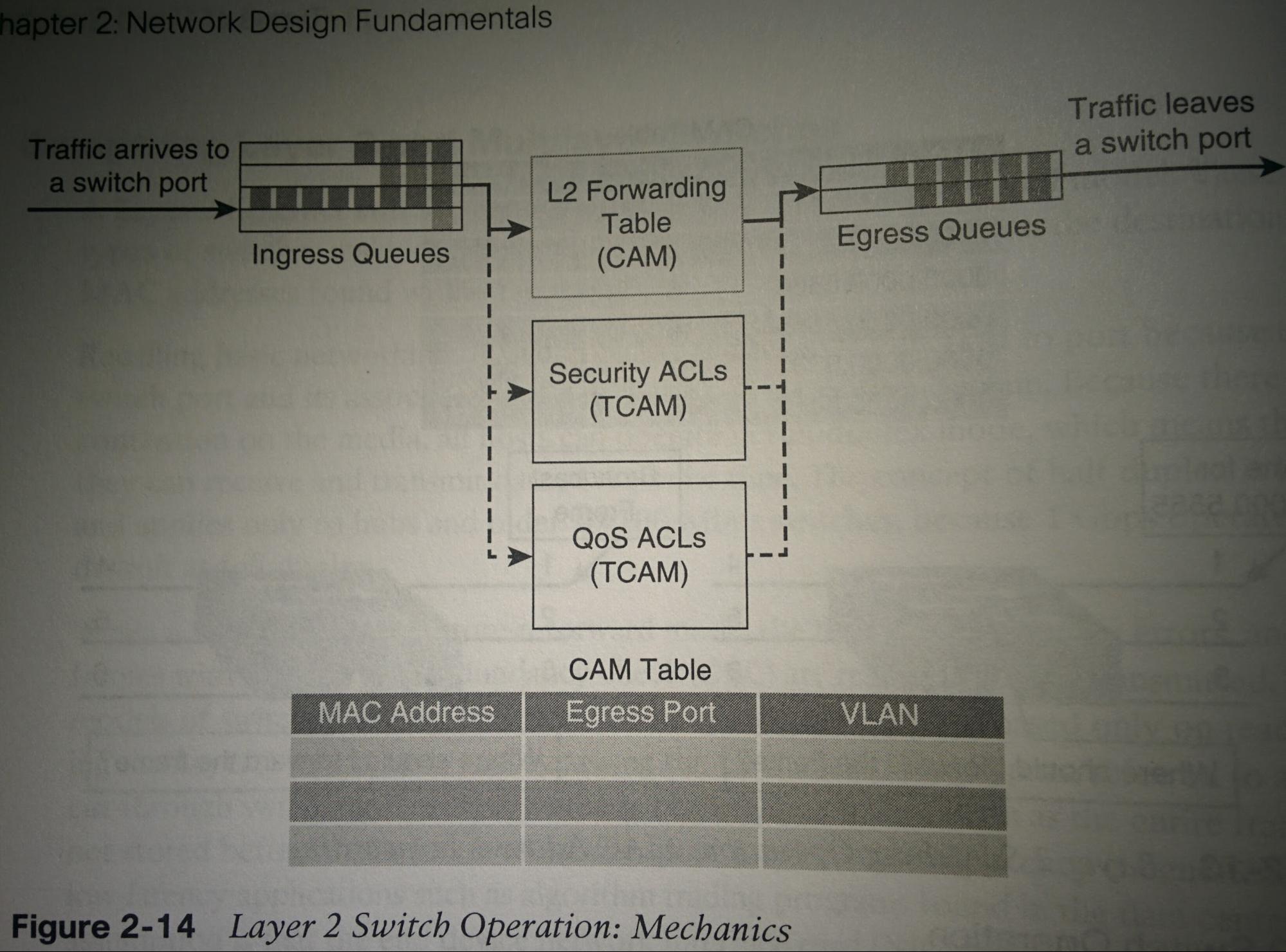
- Switching Process:
- Place in input queue, use logic to find destination, check if restrictions, check if need any QoS markings applied.
- Switching Process Step 1 (queue):
- When first receiving a frame, the S will put that frame in an “ingress queue”. Each port can have many ingress queues for different types (typically for QoS).
- Switching Process Step 2 (logic):
- first evaluate the SA (Source mac Add). If SA found in CAM Mac add-table (forwarding table), reset that entry’s aging timer. Else add it to the CAM mac address-table.
- If DA (Destination mac Add) is found in the CAM (mac add-table) to reside on a different int (different than the int received on) (known unicast):
- Forward:
- Send the frame as a unicast frame out the interface mapped to the DA.
- If DA is mapped to the same int that the SA is mapped to:
- Filter:
- A S will filter a frame if both the source and destination MAC are mapped to the same int. I.e. If it comes in from g0/1, & is supposed to go out g0/1, it’s filtered (dropped). this may occur if there is a hub connected to g0/1. In which case the S can conclude that the frame has already been received by the dev that needs it. S’s will also filter inter-VLAN comm. (Technically, when a S receives a frame with a known unicast MAC address destination, it filters it out of all other ports. i.e. it is a broadcast but filters all ports but the correct destination)
- If DA is not mapped to an int (unknown unicast):
- Flooding:
- Send the frame out all ints in the same VLAN, except the SA int.
- If the DA is “FFFF.FFFF.FFFF” (broadcast):
- Broadcast:
- Send the frame out all ints in the same VLAN, except the SA int.
- Multicast Frames:
- Multicast MAC addresses exist in the following range 0100.5e00.0000 - 0100.5f7f.ffff. When a S receives a frame with a destination add in this range, it broadcasts it.
- L2 Forwarding Table:
- “Mac address-table”; A CAM table, for each entry storing the MAC add, int, and VLAN of that int. When a brand new switch is first started up, it will have a few entries in its mac address-table already. Usually 2 entries for the “CPU”. I do not know much more than this.
S# show mac address-table [dynamic] [address mac] [interface int] [vlan vlan]
- L2 Forwarding Table entries:
- A S will learn MAC addresses via looking at the source mac address field in incoming frames. These are “dynamically” learned, compared to “statically” entered. I.e. you can also manually enter mac address-table entries but this is silly to do.
- L2 Forwarding Table aging time:
- Dynamically learned mac address-table entries are retained, by default, for 300s (i.e. 5 minutes). If the S receives a frames with that source mac address before the aging timer expires, it resets that again timer for another 300s.
- Switching Process Step 3:
- Checks if there are any restrictions on forwarding the frame by running the MACs against ACL TCAM tables. (higher-end switches can also run the against the L3 IPs)
- Switching Process Step 4:
- Checks if any QoS markings that should be applied to the frame by running against QoS TCAM tables, and marking the frame if configured to.
L3 (Multiplayer) Switch Operation
- L3 Switches perform the same L2 switching operation above, but also forward based on L3 and L4 info as well. Performing the functions of a S and a R (and as a flow cache component).
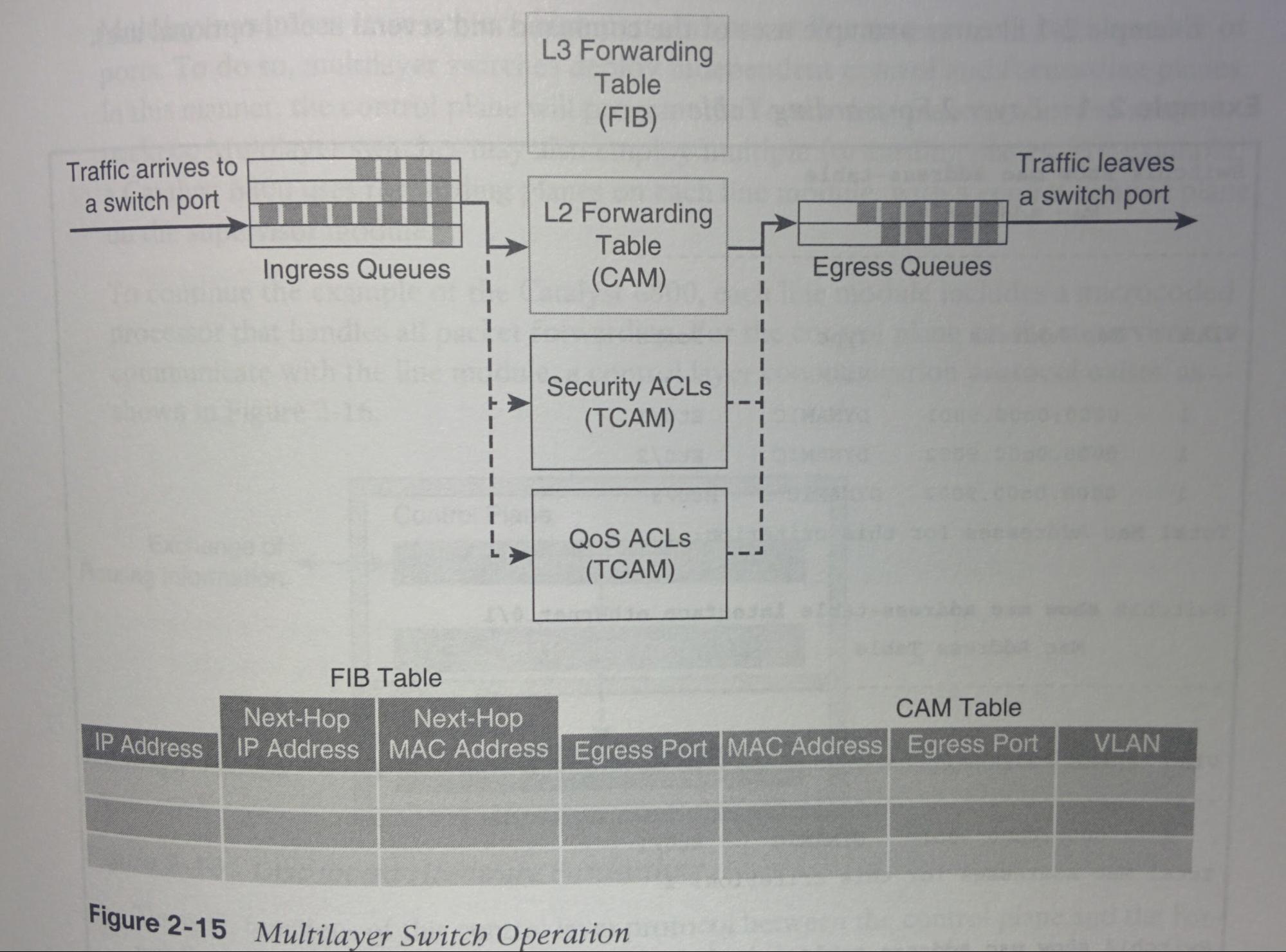
- Field rewrite:
- Many fields of a packet must be rewritten when packets are routed between subnets. (e.g. source/destination MAC add, IP header checksum, TTL, (trailer) Ethernet CRC.
- Independant Planes:
- L3 S’s deploy independent control and forwarding planes. The control plane will program the forwarding plane on how to route packets. And May employ multiple forwarding planes. E.g. a Catalyst 6800’s supervisor module has a central control plane, & a forwarding plane and microcoded processor controlling the forwarding plane on each line module.
- Communication between Planes:
- A control layer comm protocol exists. The function of which are things I do not understand (p29).
|
L3S(config)# ip routing ! Enables routing between vlans. L3S(config-if)# [no] switchport ! Use this on a L3S to configure this particular int as L2, or use the ‘no’ parameter to make it L3. |
Cisco Switching Methods
- Cisco routers (IOS or NXOS) attempt to always use CEF, falling back to Fast switching if needed, and process switching as a last resort.
- Cisco IOS-based routers use 1 of 3 methods to forward packets:
- Process switching:
- CPU/software based. Slowest.
- Fast switching:
- ”Flow-based/demand-based switching”,”route once,switch many”; L3 version is “route caching”. Process switching for the first packet, then hardware-based afterwards by caching the result.
- Requires the DA be a L3 switch int. First frame is switched in software by the route processor, because no cache entry exists yet for this new flow. The result is programmed into the hardware forwarding table (cache table), then all additional datagrams are switched in hardware (using ASICs). Entries time-out over time and are removed.
- CEF:
- “Cisco Express Forwarding”/”Topology-based switching”; Uses hardware forwarding tables for almost all forwarding. L3 version uses routing table to populate the route cache/FIB (built by the CEF facility) regardless of traffic flow.
- Uses routing table to populate the FIB (route cache). With few exceptions, all packets are (encapsulated and) switched in hardware.
- Adds enhanced support for parallel paths, optimizing load balancing at L3. With newer switches (e.g. Catalyst 4500 & 6800) not only load balancing based on source/dest IP but also TCP/UDP port numbers.
- Depending on the S, typically load balances by source-destination pair. This helps legacy applications that benefit from having all packets arrive in order. However heavy applications (e.g. firewall to webserver) won’t take full advantage of available bandwidth (polarizing), but this is less of an issue the more source-destination pairs there are utilizing the load-balancing on this dev. To solve this, new Cisco Catalyst S, by default, load balance each source IP - Destination IP - TCP/UDP port number pair, reducing the change of polarization.
- # show ip cef [ipaddr [detail]]
VLAN: Virtual Local Area Network
- VLAN:
- A VLAN is a logical broadcast domain that can span multiple physical LAN segments, and multiple switches. Benefit: segment the L2 broadcast domain, improving BW & security.
- VID:
- “VLAN ID”; The vlan number. (e.g. The VID VLAN80 is “80”)
- VVID:
- “Voice VLAN ID”; the vlan number used for VoIP traffic (e.g. VLAN9). Sometimes called an auxiliary vlan since it’s similar to trunk but not a trunk. Phone is given the VVID during initial CDP exchange.
- Total Range of VLANs: Total of 4096 (0-4095) VIDs, with 4094 usable VIDs (1-4094)
- Priority Frame: 0 ! with a VID of zero, signals that it is a priority frame. System use only, you cannot see or use this vlan.
- Normal Range VLANs: 1 - 1005
- Default VLANs: 1,1002 - 1005 ! Unable to be deleted. 1002-1005 are reserved for TokenRing & FDDI VLANs.
- Reserved: 1006-1024 ! System use only. One cannot see or use these vlans.
- Extended Range VLANs: 1025 - 4094
- Reserved (FFF): 4095 ! System use only. One cannot see or use this vlan.
- Default VLAN:
- Definition:
- When referring to the default VLAN, it is always in regards to access ints.
- If an int operating as an access int is not explicitly assigned to a VLAN, the default VLAN is the VLAN that this int will implicitly assign itself to (allowing only this VLAN to be Tx’ed and Rx’ed on it).
- On Cisco devices, the default VLAN is “VLAN1” and VLAN1 only.
- Trunk ints (somewhat related but technically not in regards to the default VLAN):
- For ints operating as trunks, if not explicitly configured for which VLANs are allowed and which are not, they will implicitly allow all VLANs to be Tx’ed and Rx’ed across it.
- By default: all ints are VLAN1 (and VLAN1 is set as the “Native VLAN”; see below).
- The default VLAN can not be renamed or deleted.
- Best Practise:
- For security, never allow the default VLAN anywhere.
- Explicitly assign all access ints to a VLAN that is not the default VLAN.
- Explicitly configure trunks to allow only the VLANs needed, and since the above rule states that all access ints should not be int the default VLAN, therefore the trunks should not allow the default VLAN.
- 802.1q Frame:
- (e.g. takes a frame sent by a host, inserts the 8021q tag in between the Src and Len/Etype fields, and recalculates the FCS field at the end)
- Requirements:
- To process an 802.1q tagged frame, a dev must enable an MTU ≥1522B (bytes). I.e. a dev must support “Baby Giant frames” which are frames between 1501B-1999B.
- Contrains:
- Dest: Dest MAC address. (6B)
- Srs: Source MAC address. (6B)
- Tag: Inserted 802.1Q tag. (4B) (the only thing added to an end user’s frame)
- EtherType(TPID): Set to “0x8100” signaling 802.1q frame is following.
- PRI: 802.1p priority field. (represented as a TCI/Tag Control Info field) (3 bit)
- CFI: “Canonical Format Identifier”; 0=EthernetSwitch 1=TokenRingNetwork. (represented as a TCI/Tag Control Info field)
- VID: The vlan id. (represented as a TCI/Tag Control Info field) (12 bit)
- Len/Etype: Specifies length (802.3) or type (Ethernet II) (2B)
- Data: Data itself
- FCS: Frame check sequence containing the CRC value. (4B) (is recalculated each time the frame is Tx, including when the frame is tagged with 802.1q)
- Modifies the 802.3 frame header, and thus requires that the FCS be recomputed.
- Static & Dynamic VLAN Assignment:
- Static VLAN assignment:
- VLAN determined by interface. Is the norm and what most are used to.
- Dynamic VLAN assignment:
- VLAN determined by MAC address. When a dev is connected, S queries a VMPS (VLAN Mgmt Policy Server) for what VLAN to assign that MAC to (regardless of port).
- End-to-end vs Local: Recommended to have 1 - 3 VLANs per access layer switch.
- End-to-end:
- Definition:
- A VLAN on switchports that are geographically disperse (across multiple buildings), requiring trunks between S’s and S’s typically operating in a VTP Svr/Cx relationship. Users are grouped by function and maintain the same VLAN if they relocate.
- IntraVLAN Routing/hop Avoidance:
- If much of the traffic in the VLAN is intra-VLAN traffic (traffic between hosts within the same VLAN) then end-to-end is beneficial in that it does not require traffic to reach a L3 device (reducing hops and conserving bandwidth). However today mode traffic is inter-VLAN, so this not much of a benefit today.
- Security/User grouping:
- Group by security level, I.e. keep HR stuff separate from sales stuff etc.
- QoS:
- Slightly easier to apply QoS with end-to-end, but can be done with local as well.
- Flooding Issues:
- However, even if a S does not have any access ports in a VLAN, with end-to-end design, the broadcast traffic will reach all switches. (unless you use VTP pruning or manually disable that VLAN off of a trunk port).
- Local:
- Definition:
- VLANs are local to the either the L2 access switch or local to the wiring closet, and connect upstream to a distribution layer L3S. If users change locations, they also change VLANs. This is called “VLAN segmentation”, and is usually the better model, since it reduces broadcast traffic. Net admins create VLANs with physical boundaries in mind rather than job functions of end users. Uses VTP transparent/off mode. Recommended to have 1 - 3 VLANs per access layer switch.
- Simplicity / Easier to manage:
- More predictable traffic flow (L2&3) assists in troubleshooting. Reduced size of failure domain.
- Smaller Broadcast domains:
- More efficient since now (compared to the past) the 80/20 rule is in play. That is ~80% of the traffic on your network will leave the segment.
- More Scalable
- Native VLAN:
- Definition:
- A per-interface configuration. The vlan that an int does not tag a frame for, and which also assumes untagged frames are for. Typically refers to trunks.
- Trunk ints:
- “Frames are Tx’ed across trunks. If that frame is in the same VLAN as that trunk’s configured native vlan, then it is Tx’ed across the trunk without an 802.1Q tag. If the device Rxs a frame on a trunk that is untagged, then it assumes it is a frame of the native vlan, and treats it accordingly.”
- Each trunk link is configured to have a “native” VLAN. If a device Rxs a frame on a trunk link that does not have an 802.1Q header on it (i.e. is ‘untagged’), the device will assume it is part of the “native” VLAN and treat it accordingly. The same is true when Txing, that is to say when a device needs to forward a frame across a trunk link, that frame will have a VLAN tag on it, if that VLAN tag is the same as the native vlan configured on the trunk link it needs to cross, then the device will forward it without a tag. Because of this, it is important that both trunk ints that connect to each other are configured to use the same native vlan.
- Access ints:
- As access interfaces use only a single vlan (possibly also the auxiliary voice vlan). The vlan assigned to that int is that int’s native VLAN, and it is sent untagged, and any traffic Rx’ed on that int is assumed to be in that VLAN.
- Default:
- By default, without configuration, all ints (trunk and access) have their native vlan set to the default vlan. (this should be changed. See “security” below)
- Security:
- For security purposes, the native VLAN on trunks should be changed to a VLAN that is neither “VLAN1” nor a VLAN that is used for other roles (e.g. data, the blackhole).
- For best security, the native vlan should not be allowed on the trunk. I.e. it should be filtered/dropped if it is untagged.
- Operational State:
- Definition:
- VLANs can be either (the default) active or suspended. A suspended VLAN exists but does not operate. A port in the VLAN suspended operational state drops all frames, until it’s set to active.
|
S(config)# vlan 999 S(config-vlan)# state {active | suspend} ! Declares a vlan’s operational state. While the “shutdown” cmd here is local, the cmd “state suspend” cmd is propagated throughout the VTP domain. S(config-vlan)# shutdown ! locally shuts down vlan. (may only take effect after ‘exit’ing, See ) S(config)# shutdown vlan #### ! locally shuts down vlan. |
- Deleting a VLAN:
- Deleting a vlan that has access ports assigned to it, will place those access ports into an inactive state that does not forward traffic. Resolve by placing them into an active vlan. See also “Operational State: Suspending VLANs” for how to shutdown a vlan and make the change propagation via VTP. Both of the below methods of shutting down a vlan are equivalent (but only 1 works while a VTP Cx). This will show in “show vlan brief” with a status of “act/lshut” rather than the normal “active” status.
|
S(config)# shutdown vlan 1 ! only this method is capable of working while in VTP Cx mode. ! or… S(config)# vlan 1 S(config-vlan)# shutdown ! this method cannot be done while a VTP Cx.
# show vlan |
- VLAN & Trunking Best Practices:
- VLAN IP addressing: Because a VLAN is a single broadcast domain, campus design best practices recommend mapping a vlan generally to 1 ip subnet.
- Trunk Pruning: Manually prune trunks of vlans not needed. If you must use VTP, use VTP pruning.
- Use local vlans: Use local vlans vs end-to-end vlans.
- Local vlan Limit: Limit it to 3 or fewer vlans per access module (furthermore, limit those vlans to a couple access & distribution switches)
- No VTP: Since you’re following best practices and using local vlans, don’t use VTP.
- No DTP: sw mode trunk/access (nothing else) Furthermore, use ‘sw nonegotiate’ to reduce convergence time.
- No ISL: 802.1q > ISL
- No telnet: Use SSH on MGMT VLANs
- No inter-Distribution: No connections between distribution-layer devices (L3S), to prevent STP loops. Simplicity > Complexity.pp
- VLAN1 =/= Blackhole: Do not use VLAN1 as the blackhole vlan for unused access ports. (use any other vlan. Typically VLAN666 is used)
- VLAN1 =/= for Data: Only allow control protocols to run on VLAN1 (e.g. CDP, STP BPDUs, PAgP, LACP, DTP, VTP, etc), this prevents DTP spoofing attacks.
- Separate VLANS: Have a separate vlan for each of the following (included are example VIDs to use):
|
VLAN Role |
VID |
Reason for mapping this VID to vlan role |
|
Default |
1 |
Unable to be changed. |
|
Voice |
9 | 411 |
Most organizations require dialing 9 to dial-out. 411 is to speak to telephone operator. |
|
Data |
80 |
Port 80 is port used for HTTP. |
|
Native |
471 | 413 |
NATIVE = N471VE/N4T1V3 = 471/413 (without Letters). 667 = almost evil (666). |
|
Blackhole |
666 |
666 is biblical mark of the beast, ie evil. Send evil to black hole to remove/contain it. |
|
Management |
999 |
Separate from most other things. No real reason. |
Native VLAN
|
S(config)# vlan 80 S(config-vln)# name NATIVE ! not required, just for documentation purposes, and ease of mgmt. S(config)# int fa0/1 S(config)# desc A_TRUNK_LINK S(config-if)# switchport trunk native vlan 80 S(config)# int fa0/2 S(config-if)# desc AN_ACCESS_LINK S(config-if)# switchport access vlan 80 S(config-if)# switchport voice vlan 9 |
_________
How to prevent untagged trunk traffic?
- What Brent does: creates the native, but just bans it from trunk ports. (sw trunk allowed vlan except 999) Because you have to have a VLAN (either vlan1 or configure to something else) but you do not have to allow it on the trunk. If you do "(config)#sw trunk native vlan 99", but do not create vlan 99, some protocols (such as UDLD) will fail.
- What I do:
|
(config)# vlan dot1q tag native ! does NOT strip the tag off of the native vlan traffic, AND drops untagged traffic. |
! See https://www.cisco.com/c/m/en_us/techdoc/dc/reference/cli/nxos/commands/l2/vlan-dot1q-tag-native.html
Attacks: See “Network Security” section for “Double-tagging VLAN Hop Attack”.
PVLAN: Private VLAN
- Private VLAN:
- https://www.youtube.com/watch?v=xl3_zgaZuH8
- Often used in service provider environments (e.g. hosted datacenters, ISPs, etc)
- Limits intra-subnet comms between hosts. Done by dividing the broadcast domains even further, while maintaining the same IP subnet. This is like having VLANs within VLANs, but they share the same IP subnet.
- Restrict comms between ports that are in the same ip subnet. (this would prevent VoIP calls between them also) they would be required to a proxy (e.g. Skype)
- This literally will block ALL traffic between hosts (not simply making them go through the L3 device/default gateway). Like an IP ACL on the S’s that says anything from x to x is killed.
- private vlans are good because then they can share the same ip address range
- compared to subnetting and wasting a ton of ip addresses using multiple broadcasts adds and network adds.
- Requirements:
- VTP mode must be either transparent or off.
- Primary VLAN:
- The mothership / mother-VLAN. The Private VLAN domain.
- Has an IP address range (aka network address for the a subnet), and all ints (within their respective secondary vlans) are within the ip address range.
- All secondary vlans are part of the primary vlan.
- Promiscuous Port(s):
- Part of the primary VLAN. Not part of any secondary VLANs.
- All secondary VLAN hosts can have comms to/from the promiscuous port(s).
- Typically the default gateway is on this port. If an FHRP is used, then there may be multiple uplink ports and therefore there may need to be multiple promiscuous ports.
- Secondary VLAN Types:
- A port can be a part of only 1 secondary vlan at any given time. It can not be a part of 2+.
- Isolated:
- There is no reason to have more than 1 isolated vlan within a single private-primary-vlan.
- Ints can communicate only with ‘promiscuous ports’.
- intra-’secondary Vlan’ comms are denied.
- Ints can not communicate with other isolated ints.
- inter-’secondary Vlan’ comms (comms to any communities) are denied.
- Ints can not communicate with any communities.
- Communities:
- Ints can communicate with ‘promiscuous ports’.
- intra-’secondary Vlan’ comms (i.e. intra-community comms) are allowed.
- Ints can communicate with other ints that are also in the same community. two ints in the same community can communicate.
- inter-’secondary Vlan’ comms (i.e. inter-community comms and comms to isolated ints) are denied.
- Ints can not communicate with other communities, or isolated ints.
|
|
Isolated |
Community |
Promiscuous |
|
What type of private VLAN is it in? |
Secondary |
Secondary |
Primary |
|
Can communicate with promiscuous ints?
|
Yes |
Yes |
Yes |
|
If another host and I are in the exact same secondary-vlan, can we talk? |
No |
Yes |
N/A |
|
Can I talk w/ secondary-vlans (regardless of type) that I’m not a member of? |
No |
No |
Yes |
- Trunks to other S:
- A
- Trunk port types:
- Standard trunk
- The ideal setup, but only if both ends of the trunk support PVLANs.
- Just like carrying non-private vlans.
- All intermediate S’es (even those that do not have any ports in any of the PVLANs) must have the same PVLAN configs in order to prevent cross-contamination (i.e. inter-PVLAN comms).
- Promiscuous PVLAN trunk:
- Used when a promiscuous port would be used if it weren't necessary carry multiple normal vlans or PVLAN domains.
- An upstream R or subint just like any other vlan traffic, Rxes traffic that is sent out through a promiscuous trunk port.
- Isolated PVLAN trunk:
- For when connecting to a S that lacks PVLAN support..
- Non-private VLANs are treated the same as a normal trunk
- isolated VLAN traffic is treated like traffic from an isolated port, it is isolated from other isolated and community traffic.
- “A S with an isolated trunk port can thus isolate between the traffic from the isolated trunk and directly connected hosts, but not between hosts connected to the non-PVLAN S.”
|
S(config)# VTP mode {off | transparent} S# show vtp status | include mode
S(config)# vlan vid-isolated0 S(config-vlan)# private-vlan isolated S(config)# vlan vid-community0 S(config-vlan)# private-vlan community S(config)# vlan vid-community1 S(config-vlan)# private-vlan community S(config)# vlan vid-primary0 S(config-vlan)# private-vlan primary S(config-vlan)# private-vlan association vid-isolated0,vid-community0,vid-community1
S(config-if)# description UPLINK_TO_DEFAULT_GATEWAY S(config-if)# switchport mode private-vlan promiscuous S(config-if)# switchport private-vlan mapping vid-primary0 [add|remove] vid-isolated0,vid-community0,vid-community1
S(config-if)# description TO_USER S(config-if)# switchport mode private-vlan host S(config-if)# switchport private-vlan host-association vid-primary0 {vid-isolated0 | vid-community0 | vid-community1}
S# show vlan private-vlan |
! This is a pre-requirement that must be done before configuring private vlans. ! Verify that VTP is either off or transparent.
! This makes it a private secondary isolated vlan.
! This makes it a private secondary community vlan.
! This makes it a private secondary community vlan.
! This makes it a private primary vlan. ! Associates vid-primary0 as the primary vlan for all of the specified private secondary vlans.
! This cmd says that this int is a promiscuous int. ! Declares the primary vlan first, then lists the range (separated by commas) of secondary vlans. If [add|remove] is omitted, add is assumed.
! This cmd says that this int is for a host in a secondary vlan. ! Sets the private primary vlan, and then the private secondary vlan.
|
|||
|
Primary --------------- vid-primary0 vid-primary0 vid-primary0 |
Secondary ------------------ vid-isolated0 vid-community0 vid-community1 |
Type --------------------- isolated community community |
Ports --------------------------------- promiscuous-int0, host-int0, host-int1, … promiscuous-int0, host-int2, host-int3, … promiscuous-int0, host-int4, host-int5, … |
|
|
S# show int int switchport | include private-vlan |
|
|||
Protected Port: “PVLAN Edge”
- Provides a feature that is similar to PVLANs, but that is supported on more devices.
- Protected ports are only locally-significant (i.e. this feature does not span more than 1 S). In contrast to PVLANs which are globally-significant (i.e. PVLANs can span more than 1 S).
- Operations:
- Traffic between protected ports (where both protected ports are on the same S) is denied, and thus must go through a L3 dev.
- Protected ports can communicate with non-protected ports without issue.
- Protected ports can communicate with any type of port (protected or not) on other S’es (because this feature is only locally significant).
|
(config-if)# switchport protected |
Subinterfaces
- Subinterfaces:
- Multiple logical interfaces on 1 physical router int. This physical interface connects to a trunk interface on a S (or sometimes a server), with 1 subinterface for each trunk.
- Only Rs support subinterfaces. Neither L2S’s nor L3S’s support subinterfaces (they use routed ports or SVIs instead).
- In large deployments, L3S’es are typically used rather than using subints and routers.
- No shut: do not 'no shut' the main int until everything is configured.
- Interface up: main int up? then all sub-ints up.
|
R(config)# interface g0/0.10 R(config-if)# encapsulation dot1q {10} [native] ! encap dot1q [x] says that this subint speaks dot1q, and tags traffic as vlan 10. R(config-if)# ip address 10.0.0.1 255.255.255.0 |
subint numbers are best to be the same as the vlan, for easy mgmt. but the encap cmd is what actually determines the vlan used.
two ways to pick native vlan
either pick one sub-int and append native the the encap cmd. eg
R(config)# encap dot1q 666 native
or
on the physical int, add an ip address and IOS will assume that as the native. But the first option is preferred.
Verification:
show ip route ! should list the sub ints.
show vlans ! ROAS us for multiple VLANs on one int.this cmd will show which vlans are on which subint and int. also tells what is native.
do those vlans exist, or have they been pruned by VTP? STP blocked?
(subinterfaces are only available on Rs, not on L3S’es)
- Benefits of subints/ROAS:
- simple to implement
- Simple to manage/troubleshoot (issue with inter-VLAN routing? there is only 1 location where the issue can be)
- works with L2S (in contrast to having to use more expensive L3S’es)
- Drawbacks of subints/ROAS:
- The R (and the single link to the R) is a single point of failure.
- Congestion may occur, especially if there is a lot of traffic between the same VLANs that go across the link to the R.
- Increased latency (the packet will have to go across the link to the R, the R will have to use software to R the packet back over the same link, and then the S must forward it again.)
DTP: Dynamic Trunking Protocol
- DTP:
- “Dynamic Trunking Protocol”; Switches use DTP to determine if an int will be access or trunk, and if trunk then what encap (dot1q | ISL). Cisco proprietary.
- DTP Ads:
- Every 60 seconds advertises the status of int, & DTP type.
- Administrative Mode:
- We configure the Administrative Mode with the commands below (by default is ‘dynamic-auto’), this will impact what the Operational Mode is.
- Operational Mode:
- Operational Mode is what is actually being used by the int.
- Nonegotiate:
- This configures the dev to not send or respond to any DTP messages (compared to simply setting an int to access/trunk which would still reply to DTP msgs sent to it). nonegotiate improves convergence time by ~2 seconds.
|
S(config-if)# switchport mode {trunk | access | dynamic-auto | dynamic-desirable} ! Sets “Administrative Mode” of the int. ! If Administrative mode is “access” or “trunk” this causes a static “Operation Mode”. ! If Administrative mode is “dynamic-*” its “Operational Mode” will change depending on what it is connected to.
S(config-if)# switchport mode trunk ! Sets administrative mode to “trunk”, which causes a static operational mode of trunk. S(config-if)# sw trunk encap {negotiate | dot1q | idl} ! Default = negotiate, if “sw trunk encap negotiate” Cisco switches try use IDL, else they use whatever both S support.
S(config-if)# switchport nonegotiate |
- Best Practise:
- Do not use DTP. Statically set all interfaces to either trunk or access. Furthermore, use ‘switchport nonegotiate’ on all interfaces. Set unused VLAN native to prevent DTP spoofing attacks.
- Attacks:
- See Network Security section for “Switch Spoofing Attack”.
VTP: VLAN Trunking Protocol
- VTP:
- “VLAN Trunking Protocol”; Cisco proprietary L2 protocol (does not travel across routers) to manage (add, rename, remove) VLAN info across all switches in a VTP domain within a single LAN. A S can be in only 1 VTP domain at a time. The VTP VLAN DB is synced across all devices in the VTP Domain / VLAN management domain.
- VTP Messages:
- Svr sends summary-ad, Cx replies with ad-request, Svr responds with 1 summary-ad and then subset-ads.
- VTP Summary Ads: Either as soon as the VTP DB changes, or (by default) every 5m (whichever comes sooner) VTP servers and Cx’s will tx VTP ads across trunks via the native-vlan to multicast MAC 0100.0CCC.CCCC (because C is for Cisco; add used also by CDP). if same domain, same PW, and greater revision number, the Rx’er will accept it, else disregards.
- VTP ads contain the following:
- VTP Domain Name
- VTP Config revision number
- Checksum (I believe)
- How a dev will process a rx’ed VTP Summary Ad:
- If VTP domain different: disregard it.
- If VTP domain is same: Evaluates the Config Revision Number….
- If configuration revision number is the equal or lower to it’s own: it will be disregarded.
- If configuration revision number is greater (higher): the dev will reply with a “VTP Adv request”. The server then responds with an additional VTP Summary Ad, and
- VTP Subset Ads: “if config revision number incremented and it sends a summary ad, one or more subset ads will follow”
- What: Contains VLAN DB info (may require multiple VTP subset ads if many vlans are present).
- How used: Server gets a VTP ad request, sends 1 summar-ad and then subset ads.
- VTP Ad Request:
- Used in response to a same-domain higher-revisionNumber VTP Summary Ad to requests the updated VLAN DB from the VTP server be sent to it via VTP Subset Ads.
- VTP Competitor:
- Multiple Registration Protocol (MRP).
- VTP Domain:
- Sometimes called a “VLAN Management Domain”. Does not span across L3 devices.
- VTP DB:
- “VTP Database”; Contains the VLAN DB (housing all of the VLANs, their numbers, names, and operational state) as well as VTP parameters (VTP version, pruning, domain, PW, etc).
- VTP Modes:
- Server: The default mode
- VTP Ads:
- Once VTP domain name declared/learned, (if VTPv1/2) will tx their VTP config via VTP ads over trunks to other S’s in the VTP domain. Many VTP servers can exist in a single VTP domain. In VTPv1/2, any VTP server can be used to make changes to the VTP DB because VTPv1/2 servers both create and forward VTP ads, while in VTPv3 only the “primary server” can configure the VTP DB.
- VTP DB Permissions:
- VTPv1/2 Servers have RW (read-write) access to the VTP/VLAN DB & VTP parameters (VTP version, VTP pruning) for the entire VTP domain. While VTPv3 have RO.
- VTP DB Location:
- Saves VTP info in “flash:/vlan.dat”.
- Cx/Client:
- Similar to a VTP server, but has only RO access to VTP DB, and relies on ads to update it.
- VTP Ads:
- Tx’s & forwards VTP ads. Can’t update own VTP DB, rather must rx VTP ad with greater config revision number for VTP DB to be updated.
- VTP DB Permissions:
- Has RO access to the VTP DB.
- VTP DB Location:
- VTP info stored only in “flash:/vlan.dat” (not running-config).
- Transparent:
- Essentially turns off VTP on the dev, but under certain conditions will forward Rx’ed VTP ads. Can use extended range vlans since it does it’s own thing.
- VTP Revision #:
- Transparents always have revision number of 0.
- VTP Ads:
- When Rxing VTP msgs on a trunk, VTP transparent switches will broadcast the VTP ad out all other trunks if both conditions of the VTP ad are met.
- The transparent S’s VTP domain is either “null” or the same as the VTP ad.
- If the transparent S’s VTP domain is defined, then the VTP adv must have the same VTP domain
- Else if the VTP transparent S’s VTP domain is not defined (i.e. is null) then it will not worry about the VTP domain of the VTP ad
- If VTPv1, requires same VTP version (The ad and the transparent S share the same VTP version). (does it forward vtpv3 ads?)
- VTP DB Permissions:
- Has no access to VTP DB. Uses a local VLAN DB rather than one from VTP. Does not adv it’s VLAN DB nor update it from Rx’ed VTP ads.
- VTP DB Location:
- VTP info stored in both “flash:/vlan.dat” and running-config (if VTPv3 and using extended range VLANs, it will only be stored in “flash:/vlan.dat”).
- Off:
- Similar to VTP transparent but it will never forward Rx’ed VTP ads.
- Availability:
- Only available if the S supports VTPv3, however VTPv3 is not required to be used in order to enable “VTP Off” mode.
- VTP Ads:
- Never creates or forwards advs.
- VTP DB Location:
- If using VTPv3 & Extended-range VLANs:
- Stored exclusively in “flash:/vlan.dat”.
- Else:
- VTP info stored in both “flash:/vlan.dat” and running-config.
- VTP Configuration Revision:
- Number used to tell track new VTP info, used to tell if a VTP adv is newer. Starts at 0 (zero). If one enters VLAN config mode and makes changes, as soon as one exists VLAN config mode the VTP config revision number is incremented by 1. In VTPv1 & VTPv2, the highest VTP config number’s VTP DB is propagated throughout the VTP Domain. However in VTPv3, a “primary server” is the only device allowed to make changes, and those changes will propagate even if there is a higher VTP configuration revision number. In VTPv3, other non-”primary server”s are not allowed to assert their DBs even if their revision numbers are higher. Incremented when S becomes a VTPv3 primary server.
- Resetting:
- Can reset the revision number to 0 by: Changing to transparent and back, or changing the VTP version number, or changing the VTP domain and back.
- VTP Checksum:
- Rxing VTP msgs with equal revision number but different checksum, reports error.
- VTP Versions:
- For best compatibility/stability all devs in VTP domain should use the same VTP version. Transparent won’t forward ads if dif VTP version. Changing version reset VTP configuration revision number. Changing the VTP version on the VTP server will propagate the change through the VTP domain.
- VTPv1:
- Default VTP version. Transparents will not forward ads if diff version number. VTPv1 servers/clients only support normal range vlans.
- VTPv2:
- VTPv2 Servers/Cx’s use only normal range VLANs (1-1005). VTPv2 Transparent & “off” (no vtp) can use normal range vlans + extended range vlans (1006-4095).
- Added Transparent forward any Version:
- Transparent S’s now forward ads even if different version number.
- Added Consistency Checks:
- Entering info via CLI or SNMP (not VTP ads or reading startup-config), checks that VLAN names & values are consistent (what does this even mean?).
- Added Token ring support:
- Now support Token ring (and it’s vlans).
- Added Unrecognized TLV:
- Now stores VTP messages (in nvram) and forwards them even if it does not understand it’s TLV (type-length-value) rather than dropping it.
- VTPv3:
- Requires 12.2(52)SE and later. See Cisco VTPv3
- Added Extended VLAN Support:
- Servers and clients now also support extended range vlans, 1017 - 4094. (not all extended range vlans as some are still reserved, see VLANs)
- Removed ‘domain learning’:
- Will no longer adopt the VLAN domain from ads if own is “null” as VTPv2 (v1?) would. For security purposes.
- Primary Server:
- A role that only a single switch in the VTP domain may have, which grants it exclusive RW access to the VTP DB. Compared to VTPv2 which gave RW access to all VTPv1/2 servers. Primary Server role is a “runtime-state”, meaning it is requested via privileged exec mode rather than in the config, and it is relinquished when it is reloaded or when another (secondary) S attempts to become the primary server.
- Secondary Server:
- A server that is not the primary server, but it will still be able to become the primary. All VTPv3 Servers become secondary upon reload. Has RO access to VTP DB.
- VTPv2 Compatibility:
- VTPv3 S will send both v3 and v2 compatible msgs at the boundary border. (if v3 receives v2 message, drops)
- VTP Domain Req:
- Requires VTP domain be configured (I believe before other configure can be entered)
- PW Encryption:
- Adds ability to encrypt the VTP password locally and during txion with MD5 ‘asymmetric’ encryption, preventing it from being displayed in plain-text via ‘show vtp password’.
- Prune Norm VLANs:
- Can only prune normal-range VLANs.
- Private VLAN:
- Allows propagating private VLAN info (only if running “IP Base” or “IP Services” feature set)
- RSPAN VLAN Support:
- Now supports RSPAN VLANs.
- Opaque DBs:
- Has the framework to allow transport other DBs besides the VLAN DB, including the MST/MSTP DB (a type of STP used when many VLANs) in seperate instance.
- Suspending VLANs:
- Suspending a VLAN on a VTPv3 Primary Server, will propagate to both VTPv3 and VTPv2 clients.
- Disabling VTP per-port: Can now disable VTPv3 on a per-port basis with “S(config-if)# [no] vtp” cmd.
- Version Interoperability: Best if all devs in the vtp domain are using the same version. In general, clients can be 1 version less than the server.
|
Compatibility |
v3 Server |
v2 Server |
v1 Server |
|
v3 Client |
Yes |
No |
No |
|
v2 Client |
Yes* |
Yes |
Yes |
|
v1 Client |
No |
No |
Yes |
* VTPv3 Servers can be compatible with VTPv2 clients/transparents, but only if not using private-vlans or extended-vlans (because VTPv2 does not support those), by sending scale-down version of VTP ads in addition to the regular VTPv3 ads, however these VTPv3 ads will not be forwarded.
- NOTE: The revision numbers will probs be different, as usual VTPv2 Cx’s won’t accept lower revision numbers from the VTP Svr (regardless of version) until they are greater than the VTPv2 Cx’s config revision number.
- NOTE: VTPv2/1 Switches do not forward VTPv3 ads. Best to place them at the edge of the VTP domain.
- NOTE: When a VTPv2-capable S operating in VTPv1 Rx’s a VTPv3 ad, it changes to VTPv2.
- See https://www.cisco.com/c/en/us/td/docs/switches/lan/catalyst3750x_3560x/software/release/12-2_55_se/configuration/guide/3750xscg/swvtp.pdf
- VTP Info save location: If VTP mode server or Cx, then VTP info saved to “flash:/vlan.dat”. Else if VTP mode off or transparent, then saved to running-config. Only “off” & “transparent” will make VLANs be listed in the startup/running-config, while all others will store them in “flash:vlan.dat” , which you can see with “dir” vlan.dat stores all ‘vtp’ & ‘vlan’ commands. Eg ‘vtp domain x’,’vtp password’, ‘vtp mode server’,’vlan 99’,’name MGMT’. etc.
- VTP Bomb: For example, when you add a new S to a LAN and it had a higher VTP configuration revision number already on it and the wrong VLANs, and all existing S’s in the LAN take on that VTP DB (with the wrong VLANs) and it blows up the entire LAN like a bomb. Typically less common on VTPv3 instances, compared to VTPv1/2.
|
S(config)# vtp domain {null} ! Set the case-sensitive domain name for vtp S(config)# vtp mode {server | client | transparent | off} ! Set the mode, default is server. Typically CoreS=Server, Distribution/AccessS=Client.
S# show vtp status ! (will show info, mode, pruning, etc.)
S(config)# vtp pruning ! Enables vtp pruning. Default is disabled. S(config)# vtp version {1|2|3} ! But transparent won’t forward if different version, else v1 server & v2 client are fine S(config)# vtp password {null} [hidden | secret] ! Sets password. Recommended to avoid “VTP bombs”. VTPv3 encrypts this with MD5 if using [hidden?]. Length must be 8 - 64 chars. S# vtp primary {vlan|mst|force} ! THIS IS CONFIGURED IN EXEC MODE! NOT CONFIG MODE! (default=vlan , if omitted) A separate primary server can exist, 1 for vlan & 1 for mst. force=skips checking for other primary servers (avoid this, causes multiple primary servers causing VLAN DB inconsistencies) becoming primary server increments config revision number. Will check for conflicting VTP3 devices, then ask to confirm before becoming primary server.
S# show vtp status | i primary ! Shows MAC & desc of current VTPv3 Primary Server (if 0000.0000.0000 then none exists)
S# show vtp password ! Shows vtp password in plain text (v3 can prevent this). S# show vlan [brief] ! (Verify revision is >~2, Number of existing VLANs >~1) S# show int trunk ! Use to verify VTP Pruning removes ‘sw tr allowed vlan’ s from a trunk link that does not need it on other end of trunk or downstream via that trunk. Shows Encap, native vlan, allowed vlans.
|
See https://en.wikipedia.org/wiki/VTP
VTP Pruning
Enabled on vtp server, and then this change is propagated throughout trunks in vtp domain to make vtp pruning enabled on all servers & clients (heard is best not to use if you have transparent switches in your vtp domain.)
- Potential VLANs:
- VTP Pruning can only prune normal range VLANs. Not Extended.
- How it works:
- if a S in a vtp domain does not have any ACCESS PORTS in a vlan, AND IT DOESN’T HAVE ANY DOWNSTREAM DEVICES THAT NEED THAT VLAN, it will send message across other trunk links to “prune”/remove that vlan off of said trunk link. so other S (on other end of that trunk) can remove that vlan from the 'sw trunk allowed vlan’ list. Benefit? that vlan’s broadcasts domain is reduced, broadcasts do not go where there is no need for them to go.
- Enabling VTP Pruning:
- Make sure, if enabling pruning on one VTPv2/1 server, to enable it also on all other VTPv1/2 servers in that VTP domain.
S(config)# vtp pruning
- How to tell where a vlan’s broadcasts will go?
S# show int trunk
- How tell if VTP pruning enabled?
S# show vtp status
- How tell if two S have synchronized?
S# show vtp status ! Look at ‘Config last modified by {ip}’ with timestamp(NTP would help here), ‘Local updater ID is {ip}’, and ‘Config Revision {#}. …
! MD5 Digest: MD5 hash of VTP Domain Name + VTP Password. If these are not identical across S, they will NOT synch.
NOTE: PVST still runs for the vlan even if that vlan has been pruned from the switch, because a S will still know of the vlan. Pruned =/= forgotten.
802.1D (STP) & 802.1W (RSTP)
- Spanning Tree Algorithm:
- “STA”: used to determine which ports are blocking/standby and which are forwarding within a L2 domain. Blocks/places in standby so there is only 1 active path to each network segment (preventing issues when there are redundant links in a L2 segment).
- MST:
- “Multiple Spanning Tree”.
- STP:
- Supports only 1 VLAN.
- PVST(+):
- Per-vlan STP. Support multiple VLANs, but is Cisco proprietary. PVST became obsolete when Cisco introduced PVST+.
- CST:
- Common Spanning Tree. 1 STP instance for the entire network. Supports multiple VLANs.
- Issues solved by STP:
- Where this issue could occur:
- In a network with redundant L2 links.
- For example: 3 switches where each S is connected to the other 2 S’es with L2 links.
- For example: 2 switches with 2 (or more) L2 links between them.
- Broadcast storms:
- When a broadcasted frame causes exponentially more broadcasted frames, which cause exponentially more broadcasted frames…. etc. etc.
- E.g. S1 broadcasts a frame out of ints G0/1 - 2 (both of which connect to S2). S2 gets the first broadcast frame, via G0/1, and broadcasts that out both ints (G0/1 & G0/2), then receives the original broadcast frame again on G0/2 and repeats it actions. Now S1 will receive the same broadcast frame 4 times. This causes an exponential loop of broadcasts, and is called a “Broadcast Storm”.
- MAC table instability:
- Same example as above, but each time a S receives one of those frames from the other S’es, it will update its MAC add table to list ‘the link it receives the frame on’ as the int that connects this S to the other S. This continues and in situations with more S’es it will end up with a MAC add table that lists the wrong ints as connecting to the wrong devices.
- Multiple frame transmission:
- Same example as Broadcast storms, where the same frame is received by a host multiple times. E.g. in a multi-host game, player tells S to move character 1 unit forward may result in the character moving multiple units forward due to the S receiving the same “move forward 1 unit” frame multiple times.
- BID (Bridge ID):
- BID = ((Priority + VLAN) + MAC). lower is better. 8-byte, with 2 bytes for the priority value (Priority + vlan) and 6 bytes for the “system ID” AKA the MAC address.
- BP (Bridge Priority):
- A range between 0 and 61440 where lower is better. Rises from 0, in increments of 4096 (because the priority is combined with the VLAN when creating the BID, & there are 4096 total VLANs). Default = 32768. You can change this. As noted in the “BID” definition, if tie, S with the lowest MAC address is better.
- RB (Root Bridge):
- What is it?
- The S with the lowest BID (the best/most desirable BID) becomes the RB through the STP Election process.
- How different?
- All RB ports are DP (Designated Ports / not blocked by STP).
- Who should be the RB?
- Best the make the most upstream S (i.e. the S logically closest to the core layer) be the RB, if tie then the most powerful S (the S that can forward the most amount of packets).
- RBID (Root Bridge ID):
- The BID of the RB. (i.e. for S2, their RBID is the BID of the S that they currently believe is the RB).
- PC (Port Cost):
- What is it?
- The * Current ACTUAL speed * of an int. Not the max speed of an int, the current ACTUAL speed, look for manually configured speeds.
- Lowest PC is more desirable.
|
Current Actual Ethernet Speed * |
(Cisco default) IEEE 1998 Cost: |
IEEE 2004+ Cost |
|
10 Mbps |
100 |
2,000,000 |
|
100 Mbps |
19 |
200,000 |
|
1 Gbps |
4 |
20,000 |
|
10 Gbps |
2 |
2,000 |
|
100 Gbps |
N/A |
200 |
|
1 Tbps |
N/A |
20 |
- RC (Root Cost):
- The total aggregate PC (Port Cost) between a S and the RB. (i.e. cost for a S to send a frame to the RB, which includes each ?outgoing? interface (because there are 2 ints on each link, only the int that is Tx’ing the frame will increment the PC, not the Rx’ing int)).
- RP (Root Port):
- Port on a S with the least RC compared to its other ports. Unblocked port (forwarding) that leads to the Root Bridge.
- DP (Designated Port):
- Port that forwards, but is not the RP.
- Non-root bridges will compare port costs of redundant links, and use the lowest cost redundant port rather than the more costly port. So once it is determine what link will be blocked (the one with the higher PC(port cost)) which int on the link do we put into blocking state? The one on bridge with the lower BID.
- STP is only run on ports in a connected state. Ports that are Administratively Shutdown, or are not connected, are placed into “STP disabled state”.
- PID (Port ID):
- (Port Priority + Port Index).
- Port Priority:
- Default is 128? Need more info on this.
- Port Index:
- (e.g. Assuming same Port Priority, Fa0/1 is lower, and therefore better, than Fa0/99)
- Timers:
- Hello timer
- MaxAge timer
- Forward Delay timer (default 15s ?)
- BPDU:
- “Bridge Protocol Data Unit”; Used for communication between bridges/switches.
- Hello BPDU:
- The most common BPDU. Listing many details including the sender’s: RB timers, RBID, RC, BID, and Port ID.
- Superior Hello BPDU: A Hello BPDU listing a (numerically) lower/better RBID. A BPDU is superior if it has:
1. Lower RBID; if tie ...
2. Lower RC; if tie ...
3. Lower BID; if tie ...
4. Lower Port ID
- Inferior Hello BPDU: A Hello BPDU listing a (numerically) higher RBID.
|
S(config)# spanning-tree mode {rapid-pvst | pvst} ! Configures the STP mode. Default = ”pvst” (per-VLAN Spanning Tree). ! identify which mode, RSTP/MST = rapid, ieee = STP. S(config)# spanning-tree vlan # priority 32768 ! Configures the priority (and subsequently the BID) of the switch for this vlan. This can be 0 - 61440 (default = 32768). S(config)# spanning-tree vlan # root {primary | secondary} ! this sets pri to become RB, now ,, not continuous changes, just now, ! LOGIC: what RB pri? if RB pri >24576, set my pri 24576. ! if RB pri <=24567, set my pri JUST low enough to become RB ! If “... root secondary” then configures the S with the 2nd lowest priority. |
- Blocking Port:
- does not forward frames besides STP msgs and some other overhead msgs. Do not learn MAC address from received frames.
- STP Election Process:
- All S’s begin by Txing Hello BPDUs listing their BID as their RBID. When a S receives a “Superior Hello BPDU” (with a lower RBID), it will then list that RBID as it’s RBID, and use this in future Hello BPDUs that it transmits. Eventually all S will have the same RBID (per VLAN).
- Process:
- All S consider themselves as the RB and Tx out BPDUs every 2 seconds (by default) listing itself as the RB and listing its BID as both the sender’s BID and its BID as the RB’s BID. When a S receives a BPDU listing better BID, this S will now consider that S the RB and list that S as the RB in its BPDUs. …. STP elects the S with the best BID as the RB, and all of the RB’s ints are put into the forward state (are not blocked). All other Ss determine the least costly route (route to RB with the least total port cost), and put the int they use for the route into the forwarding state and this int is this S’s RP
|
! Enabling PortFast = enabling RSTP point-to-point edge ports (bypassing listening & learning states)
! BID = (Priority + VLAN) + MAC ! How S picks RP? Lowest RC, BID, port-pri, port# S# debug spanning-tree events ! Lists port and role changes
S# sh spanning-tree int F0/1 detail ! tons of stuff, if portfast, if BPDUGUARD, BLDUs Tx/Rx S# sh spanning-tree int F0/1 portfast ! lists vlans w/ portfast on that int S(config)# spanning-tree vlan # priority 32768 ! set pri of S S(config)# spanning-tree vlan # root primary ! this sets pri to become RB, now ,, not continuous changes just now, ! LOGIC: what RB pri? if RB pri >24567, set my pri 24576. ! if RB pri <=24567, set my pri JUST low enough to become RB
S(config)# spanning-tree vlan # root secondary ! becomes 2nd lowest pri
S# debug spanning-tree events ! shows when ports change states, & more S# sh spanning-tree [vlan 99] bridge ! BID breakdown :) + timers OR sh spanning-tree bridge S# sh spanning-tree [vlan 99] root ! per vlan, show RID, MAC, RC, timers, RP ,, or sh spanning S# sh spanning-tree [vlan 99] ! sh RB pri, mac, timers, & same for this S & this S's ints S# S(config-if)# spanning-tree pri 32768 ! Set priority of int all vlans (not configured with the "if)# spanning-tree [vlan 99] priority 32768"
S(config-if)# spanning-tree [vlan 99] priority 32768 ! set priority value of int in vlan
! BID = (Priority + VLAN) + MAC
! There are 2 types of etherchannel, L2 & L3 S# show etherchannel summary ! to determine if L2 or L3 etherchannel.
! Enabling Portfast = enabling RSTP point-to-point edge ports (bypassing the listening & learning states)
|
802.1D/STP Port Costs
|
Ethernet Speed * |
IEEE Cost: 1998 |
IEEE Cost: 2004 |
|
10 Mbps |
100 |
2,000,000 |
|
100 Mbps |
19 |
200,000 |
|
1 Gbps |
4 |
20,000 |
|
10 Gbps |
2 |
2,000 |
|
100 Gbps |
N/A |
200 |
|
1 Tbps |
N/A |
20 |
* Current ACTUAL speed, not the max speed, the current ACTUALLY CONFIGURED speed, look for manually configured speeds.
(Timers)
Hello Timer: How often Tx BPDUs (by default 2s)
Forward Delay: Delay to move forward from LISTEN/LEARN port states
MaxAge: How long til ‘not hear from RB’ til begin reconverge
|
DEFAULTS |
Hello Timer |
Forward Delay |
Max Age |
|
802.1D / STP |
2s |
15 |
10 * Hello (=20s) |
|
802.1W / RSTP |
2s |
? |
3 * Hello (=6s) |
These are the default timers
In network, they are determined by the RB.
RB tells other Ss, what timers to use.
802.1W / RSTP
Adds a new mechanism to replace the root port, without any waiting to reach a forwarding state (in some conditions)
Adds a new mechanism to replace a designated port, without any waiting to reach a forwarding state (in some conditions)
Lowers waiting times for cases in which 802.1W/RSTP must wait
RSTP is backwards compatible with STP.
How do I change to RSTP?
go to all S’s and do:
spanning-tree rapid per vlan ???
802.1W / RSTP: Port Roles
Alternate port:
Alternative RP (Must be receiving ‘BPDUs w/ same RB’ as RP) Moves immediately to Forwarding-State/RP when RP hits MaxAge.
Backup port:
(rare) Backup DPs
802.1W / RSTP: Port States
|
802.1D |
802.1W |
Function |
|
Disabled |
Discarding |
Port is Administratively-down |
|
Blocking |
Discarding |
Control traffic only (CDP, LACP, DTP, etc) |
|
Listening |
(not used) |
Tx/Rx BPDUs, STP participation, flushes MACs |
|
Learning |
Learning |
Learning MACs to add to MAC-add-table |
|
Forwarding |
Forwarding |
all (also learns MACs) |
802.1W/ RSTP: Port Types
if Full Duplex -> Point-to-Point (P2p)
if Half Duplex -> Shared (Shr)
then if PortFast enable -> Edge
eg if Full Duplex & Portfast -> P2p Edge
Shared ports: rare, but used when shared ethernet/collision domain, eg connecting to hubs. Converges slower compared to P2p
Warning: Cisco recommends AGAINST Shared-Edge ports, as it may cause loops!
|
S# sh spanning-tree ! will list what type each port WILL BE IF RSTP IS ENABLED. ie will list (eg shr) even if configured as pvst |
(PortFast)
|
S(config-if)# spanning-tree portfast disable ! PortFast statically: off , this overrides the default S(config-if)# spanning-tree portfast ! PortFast statically: on (to set to default, just prefix w/ no) S(config-if)# spanning-tree portfast disable ! PortFast statically: off , this overrides the default S## sh spanning-tree int F0/1 portfast ! if int is up, will tell if portfast is active S# sh spanning-tree int F0/1 detail ! much info, if portfast enabled
S(config)# spanning-tree portfast default ! All ints enable portfast by default, go to trunks and disable w/ "spanning-tree portfast disable" |
??????
STP & RSTP
S(config)# spanning-tree mode [rapid-pvst | pvst] ! choose stp mode, default=pvst
! identify which mode, RSTP/MST = rapid, ieee = STP.
! Enabling PortFast = enabling RSTP point-to-point edge ports (bypassing listening & learning states)
! BID = (Priority + VLAN) + MAC
S# debug spanning-tree events !
S# sh spanning-tree int F0/1 detail ! tons of stuff, if portfast, if BPDUGUARD, BLDUs Tx/Rx
S# sh spanning-tree int F0/1 portfast ! lists vlans w/ portfast on that int
S(config)# spanning-tree vlan # priority 32768 ! set pri of S (32768 is default)
S(config)# spanning-tree vlan # root primary ! this sets pri to become RB, now ,, not continuous changes just now,
! LOGIC: what RB pri? if RB pri >24567, set my pri 24576.
! if RB pri <=24567, set my pri JUST low enough to become RB
S# debug spanning-tree events ! shows when prorts change states, & more
S# sh spanning-tree [vlan 99] bridge ! BID breakdown :) + timers OR sh spanning-tree bridge
S# sh spanning-tree [vlan 99] root ! per vlan, show RID, MAC, RC, timers, RP ,, or sh spanning
S# sh spanning-tree [vlan 99] ! sh RB pri, mac, timers, & same for this S & this S's ints
S# S(config-if)# spanning-tree pri 32768 ! Set priority of int all vlans (not configured with the "if)# spanning-tree [vlan 99] priority 32768"
S(config-if)# spanning-tree [vlan 99] priority 32768 ! set priority value of int in vlan
! BID = (Priority + VLAN) + MAC
! There are 2 types of etherchannel, L2 & L3
! Enabling Portfast = enabling RSTP point-to-point edge ports (bypassing the listening & learning states)
TO DO:
COMPARE OUTPUT FROM ALL LISTED SHOW COMMANDS ON PG 95-96
ADD IMAGES OF SHOW OUTPUTS
Commands to verify exist
S(config)# spanning-tree mode [rapid-pvst | pvst] ! set STP mode
S(config)# spanning-tree [vlan #] root primary ! changes S to RB, P changed to the lower of either 24576 or 4096 less than the priority of the current RB when the command was issued
S(config)# spanning-tree [vlan #] root secondary ! Sets this S’s STP base pri to 28672 (verify this with other notes)
S(config)# spanning-tree [vlan #] {pri #} ! Sets bridge pri of this S for the specified VLAN
S(config-if)# spanning-tree [vlan #] cost # ! Sets STP cost
S(config-if)# spanning-tree [vlan #] port-priority # ! Sets STP port pri in that VLAN (0-240, in increments of 16(lower=better))(used for RP tiebreaker if cost,&BID are same)
S(config)# spanning-tree bpduguard default ! Sets all ints (not statically overwritten) to enable bpduguard
S# show spanning-tree ! Lists details about the state of STP on the switch, including the state of each port
S# show spanning-tree int [x] ! Lists STP info just for that int
S# show spanning-tree int [x] portfast ! 1-liner, if portfast enabled
S# show spanning-tree vlan #
S# show spanning-tree vlan # bridge
S# show spanning-tree vlan # root
S# show spanning-tree summary ! Default portfast/bpduguard settings, which vlan this S is RB
PortFast
S(config-if)# spanning-tree portfast ! PortFast statically: on (to set to default, just prefix w/ no)
S(config-if)# spanning-tree portfast disable ! PortFast statically: off , this overrides the default
S# sh spanning-tree int F0/1 portfast ! if int is up, will tell if portfast is active
S# sh spanning-tree int F0/1 detail ! much info, if portfast enabled
S(config)# spanning-tree portfast default ! All ints enable portfast by default, go to trunks and disable w/ "spanning-tree portfast disable"
__
- Portfast: port goes immediately from blocking to forwarding, (no listening or learning for 802.1D/PVST)
only for edge ports/connected to end devices. Best paired with bpduguard.
BPDUguard & Filter
- Priority:
- BPDU filter takes precedence over BPDU guard. So doing both on the same switch makes only BPDU filter take effect (THIS CAUSES LOOPS. DON’T FUDO THIS).
S(config-if)# spanning-tree bpduguard enable ! overrides default, statically enabling BPDUguard on int
S(config-if)# errdisable recovery cause bpduguard ! automatically recovers from bpduguard-caused-errdisable state
S(config-if)# errdisable recovery interval 400 ! ^... after this amount of s.
S(config-if)# spanning-tree bpduguard disable ! overrides default, statically disabling BPDUguard on int
S# sh spanning-tree int F0/1 detail ! much info, if bpduguard enabled, BPDUs Tx/Rx
S(config)# spanning-tree portfast bpduguard default ! all ints, that arn't statically configured, enable bpduguard
S# sh spanning-tree summary ! much info, if portfast is default, if BPDUguard default
- BPDU Filter:
- Never use this. Very few situations where you want this, such as an IDS/IPS/Wireshark/network monitoring device on a port.
- Root Guard:
- Blocks a port if the STP BPDUs would change the election / change the election. But will unblock if it stops.
Port-Channel / EtherChannel
- Terminology:
- No definitive answer.
- EtherChannel:
- Cisco proprietary term used to discuss the technology as a whole. Logical bundle of multiple ethernet physical links.
- Port-channel:
- (“po”); The virtual int that is an instance of an EtherChannel. The NX-OS line uses port-channel (sometimes un-hyphenated) almost exclusively.
- Port-Channel:
- Up to 8 redundant links may be bundled into 1 logical link.
- Best Practice:
- Verify that the ints (without being in an etherchannel) are working properly (‘show ip int brief’ UP/UP)
- Shutdown the ints to be put into an etherchannel first before you begin configuring them.
- Reset the ints to default settings via “default int range Fa0/1 - 2”. But then add descriptions to the individual ints beforehand.
- Keep the locally significant ‘channel-group #’ numbers to the same on both ends of the link, for ease of mgmt/troubleshooting.
- PO Inheritance:
- A newly created port-channel (interface) will inherit the config of the first int that was placed into it.
- State:
- If If PAgP int trying to form etherchannel with a LACP int, the PAgP int will gain the “I - Stand Alone” flag.
- If a PAgP int trying to form etherchannel with an “ON” int, the PAgP int will gain the “D - Down” flag (because ON does not send any msgs).
S# show etherchannel summary ! (I) = stand-alone. Means other side of PO is not in etherchannel.
- Load Balancing:
- Traffic balanced according to the Load-Balancing Hashing Algorithm (“LBHA”), and is a global cmd (all po’s on the S will use this same LBHA per L3 protocol. i.e. different LBHA can be used for IPv4,IPv6,non-IP, and MPLS. see “show etherchannel load-balance”).
- RBH:
- “Result Bundle Hash”; A 4-bit hex value (decimal 0 - 7; hex 0x0 - 0x7) that will match to only 1 po int, based on the LBHA. If a po has ≤7 ints, at least 1 int will have multiple RBH values pointing to it. While a po with 8 ints will not. (See the table below).
S# test etherchannel load-balance int port-channel <po #><mac/ip> <src add> <dest add> ! Returns the RBH hex value, like “Computed RBH: 0x5”. Some IOS’s also list what int it maps to.
S# show int port-channel <po#> etherchannel ! See the below output example.
|
S# show int port-channel 1 etherchannel |
||||
|
... |
||||
|
Index |
Load |
Port |
EC state |
No of bits |
|
-----------+---------+----------+-------------+----------- |
||||
|
0 |
49 |
Gi3/1 |
Active |
3 |
|
1 |
92 |
Gi3/2 |
Active |
3 |
|
2 |
24 |
Gi3/3 |
Active |
2 |
Look at the "Load" column corresponding to a physical interface. Convert those two separate hex values (e.g. 49 = 0x4 0x9) to the 1-byte bin value (e.g. 01001001). Do this for all ints.
= 76543210 (decimal? places for the RBH True Values below. This part is tricky so check this field often)
Load; Hex; = Binary; = RBH True value;
49 = 0x4 0x9 = 0100 1001 = 01001001 Here this byte’s 0,3, & 6 bits are set/flipped. So RBH values of 0x0,0x3, & 0x6 will Tx via this physical int in the po.
92 = 0x9 0x2 = 1001 0010 = 10010010. Here this byte’s 1,4, & 7 bits are set/flipped. So RBH values of 0x1,0x4, & 0x7 will Tx via this physical int in the po.
24 = 0x2 0x4 = 0010 0100 = 00100100. Here this byte’s 2, & 5 bits are set/flipped. So RBH values of 0x2, & 0x5 will Tx via this physical int in the po.
Notice the pattern of where the set/flipped (1)s are in the “RBH true value” field above. It revolves from int index to int index. (in the above example it goes int indexes 1,0,2,1,0,2, etc.)
This is where the “PO LB/int by # of Ints” table below comes in handy.
The “No of bits” field corresponds to the load-balancing table below, with regards to which ints receive what portion of the traffic.
- LBHA:
- “Load-Balancing Hashing Algorithm”.
- LBHAs Available:
- The LBHAs allowed depend on the S model. Models 4500 and 6500 series can load balance using (source &/or destination) port numbers, while others can not. All S models can load balance using different combinations of source/dest mac/ip.
- S(config)# port-channel load-balance ? ! to see all LBHAs available on the S.
- LBHA Logic:
- The values (src-ip value is IPs, src-mac value is macs) are hashed into binary values (e.g. 10111010), only a certain number of rightmost bits of the hash are evaluated (e.g. xxxxxxxx10) depending on how many ints are in the po (if 2 ints, we use 1 bit. if 3 - 4 ints we use 2 bits, etc.). This provides a value (e.ge 10) that is used to tell the po the int index number (of ints in the po) to Tx the frame across (ie this value tells the po which physical int to forward the datagram across).
- If 2 ints in po, then when the values are hashed only the single rightmost/least significant bit is evaluated. (0 or 1)
- If 3 - 4 ints in po, then when the values are hashed only the 2 rightmost/least significant bits are evaluated. (00,01,10, or 11)
- If multiple values are to be hashed:
- (e.g. src-dst-ip or src-dest-port, but not src-ip) then an XOR operation is performed on the hashed value’s rightmost/least significant bit(s), to determine the port index number to use to forward the datagram.
- 0 XOR 0 = 0.
- 0 XOR 1 = 1.
- 1 XOR 0 = 1.
- 1 XOR 1 = 0.
- LBHA Default: The default LBHA varies, but commonly is … (verify with “show etherchannel load-balance”)
- Non-IP: “src-dst-mac”. (MACs are the only option since non-ip lacks ip adds, and therefore lacks port numbers as well.)
- IPv4: “src-dst-ip”.
- IPv6: “src-dst-ip”.
- LBHA That’s right for me: If a group of 2 devices communicate over the po much more than others: an IP add based LBHA will saturate one link (uneven distribution). Try a port-based LBHA.
- For the most balanced traffic across all ints: Use a number of ints in the po that is equal to a power of 2. (i.e. 2,4, or 8) Since those load balance equally across all of the ints.
|
PO LB/int by # of Ints |
|
|
po ints |
LB (No of bits) |
|
8 |
1:1:1:1:1:1:1:1 |
|
7 |
2:1:1:1:1:1:1 |
|
6 |
2:2:1:1:1:1 |
|
5 |
2:2:2:1:1 |
|
4 |
2:2:2:2 |
|
3 |
3:3:2 |
|
2 |
4:4 |
- Use “show int po <po#> etherchannel”’s “No of bits” field for how that po is load-balancing across its ints.
S# show etherchannel load-balance ! Returns the current LBHA per L3 protocol (IPv4, IPv6, non-IP, etc)
S(config)# port-channel load-balance ? ! to see all LBHAs available on the S.
- LBHA Traffic Distribution per Int:
S# clear counters ! One will be prompted by IOS to confirm this action.
S# ping ! Find some way to send traffic across the po.
S# show int Fa 1/38 | i packets output ! Returns the packets Tx’ed and their total byte size. Compare this with the other ints in the po.
S# show int Fa 1/39 | i packets output ! Returns the packets Tx’ed and their total byte size. Compare this with the other ints in the po.
! Clear counters again and test in another fashion, such as to a different IP, or form a different MAC, or using a different port. A way to test how the load balancing operates.
S(config)# port-channel load-balance {src/dst/src-dst-mac | src/dst/src-dst-ip | src/dst/src-dst-port | mpls} ! Configure the device-wide LBHA.p
- VSS & vPC:
- New technologies that allow a port-channel to be connected from an access switch to 2 different distribution switches for redundancy.
- PO STP Adjustment:
- (at least with LACP/PAgP, not sure about ON) If 1 link in an portchannel drops, the portchannel will automatically adjust the po’s bandwidth, and as such, STP cost will change.
- PO STP Port Costs:
- Ints w/ different STP port path costs does not by itself cause an po-incompatible int, but it can cause other things that do.
- PO Numbering:
- PO numbers, such as “int po1”, are locally significant rather than globally significant. Although best practise would have them be the same on both ends of the po, they can differ.
- PO Protocols: Protocols add initialization delay & overhead to check for correct/matching configs on both ends, compared to “ON”. None are inter-operable.
- ON: Statically enables the po even when misconfigured, compared to PAgP/LACP protocols. Causes issues if an int fails (?) or is misconfigured.
- Mode:
- ON: Uses CDP in some fashion. Does Tx EtherChannel negotiation frames, and filters/drops all Rx’ed ones too.
- Cisco PAgP: Cisco proprietary Port Aggregation Protocol. Automatically reconfigures all ints if one int changes its speed, duplex, or vlan. (auto/desirable)
- Modes:
- Auto: Awaits unsolicited PAgP msgs. Must connect to PAgP Desirable.
- Desirable: Tx’s unsolicited PAgP msgs. Must connect to PAgP Desirable or PAgP Auto.
- Requirements: Identical allowed vlans (access or trunking).
- 802.1ad LACP: Part of IEEE 802.3ad (an open standard), and checks the ints for consistent speed, duplex, and vlan info. (ACTIVE/PASSIVE)
- Modes:
- Active: Tx’s unsolicited LACP msgs. Must connect to LACP Active or LACP Passive.
- Passive: Awaits unsolicited LACP msgs. Must connect to LACP Active.
- System Priority: S w/ lowest system priority decides which ports participate in the etherchannel. Assigned automatically but can be configured by CLI.
- SystemID: SystemID = (S’s MAC + Sys Priority)
- Port Priority: Port priority determines if an int is “active” or “standby”, used only if hitting the limit on max active ints. Assigned automatically or configured via CLI.
- Roles: LACP assigns roles to etherchannel ports.
- States: Active or Standby. Standby means it stands by waiting for an active to fail so the standby can take over.
- Limits: Max active ints in an etherchannel depend on model of S. Commonly max of 8 active ints, and max of 16 total ints (w/ 8 standby).
- Administrative Key: Each port has an admin-key, and is used to determine it’s ability to aggregate with other ints. Determined by part’s physical characteristics, such as data rate, duplex ability, medium (point-to-point vs shared). Assigned automatically or configured via CLI.
- EtherChannel MisConfig Guard: A feature used to detect EtherChannel misconfiguration, which is enabled by default.
- Operation: When the channel parameters do not match on both ends “EtherChannel MisConfig Guard” will place the individual ints into “State: err-disable” and generate a syslog msg.
S(config)# spanning-tree etherchannel guard misconfig ! (default) Enable EtherChannel MisConfig Guard
S# show spanning-tree summary | i EtherChannel misconfig guard
- L2 vs L3: There are 2 types of etherchannel, L2 & L3. Only real difference in configuration is that L3 po’s must do “no sw” on the individual ints before adding them to the po, then one must also do “no sw” on the po itself.
S# show etherchannel summary ! to determine if L2 or L3 etherchannel.
- Required Similarities:
- Speed
- Duplex
- STP int settings
- Operational state (access or truck)
- If access:
- Access VLAN (sw access vlan [x])
- If trunk:
- Allowed VLAN (sw trunk allowed vlan {x})
- Native VLAN (sw trunk native vlan {x})
- STP Impact on MAC-Add-Table: if 1 int on link is blocking, neither learns MAC of other, since neither receive data frames. Remember this is per vlan, if you do some (impromptu) load balancing by having different VLANs forward frames different ways (e.g. VLAN 80 traffic goes one way, but VLAN 9 traffic goes another) then the same S may have different entries for where to forward a frame depending on which VLAN (even if Txing to the same location). Would be wise do make sure these ints are not blocked by STP if doing a L2 po.
PO Creation
- Even adding a new int to an existing po is the same procedure as this.
!
S(config)# default int range Fa0/11 - 12 ! Best to do this to remove any pre-existing configs, even if one believes there aren't any.
S(config)# int range Fa0/11 - 12
S(config-if)# description {Po1_TO_otherDevice} ! Descriptions are nice when reading the config. Descriptions on the po do not duplicate to the individual ints.
! if L3-PO do “no switchport”. ! This also adds to “no ip address” cmd.
S(config-if)# channel-protocol {LACP|PAgP} ! (Optional) limits ‘channel-group # mode’ cmds to only the protocol you enter here in this cmd (eg pagp blocks ACTIVE/PASSIVE).
S(config-if)# channel-group {po#} mode {on|active|passive|auto|desirable} ! Adds the int(s) to the specified po (creating the po if nonexistent), using the specified EtherChannel protocol.
S(config)# int port-channel {po#}
S(config-if)# description {TO_otherDevice}
! if L3-PO do “no switchport”. ! This may automatically be added by doing the “no sw” on the individual ints.
S# show int trunk (notice port name)
S# show int [fast 0/11] (^if any are err-disable'ed, finish config then shut; no shut)
S# show int port-channel 1
S# show int etherchannel
S# show etherchannel [#] ! [#] is optional but will display only that specified po instead of all
S# show etherchannel [po1] [summary | detail | brief]
S# show etherchannel summary ! If LACP or PAgP, if L2 or L3, which ports in which po, if po is down or not`
S# show etherchannel 1 port-channel ! which protocol, which ints. Seems to be ^ but po specific.
S# show spanning-vlan 1
S# show etherchannel [#] [summary] ! [#] is optional but will display only that specified po instead of all
SPAN: SwitchPort ANalyzer
- SPAN:
- “Switchport Analyzer”; On L2 & L3 switches, duplicates frames Txed, Rxed, or both from 1 or more ints (or vlans) to a different (local or remote) switchport (usually for analysis, like Wireshark or an IDS).
- SPAN Types:
- Local SPAN:
- A S duplicates specific traffic from 1 switchport to another switchport. Both switchports are on the same S.
- RSPAN (Remote SPAN):
- Definition:
- Like local SPAN, but the source and destination are on different S’es. The S with the source of the data will place the data in a special VLAN, send that VLAN across a trunk to another S (which also has that special VLAN configured), and then that traffic will be sent to the destination. Make sure that this ‘remote-span’ vlan is not used for anything else.
- Configuration:
- Configure the vlan that is to be used for RSPAN, and use “remote-span” in it’s vlan config mode.
- Then configure the normal SPAN setup below, but with a destination of “remote vlan remote-span-vlan#”.
- Then on the receiver, do the opposite, i.e. do source “vlan vlan#” and destination, “int int-to-analyser”.
- VLAN SPAN:
- Limitations:
- Make your source as specific and limited as possible; Get all the data you need and nothing else, no fat. Understand that you can have multiple sources (multiple ints or multiple VLANs) but the destination port must be able to handle what you send it. I.e. “monitor session 1 source vlan 1 both” could be a metric fuckton of traffic (~100Gb/s ), and your wee lil g0/1 int ain’t gunna cut it. All in all, don’t obliterate your dest int.
- SPAN Destination:
- A SPAN dest int can only be used in one SPAN session at a time. I.e. if an int is a SPAN destination int, it cannot be in any other SPAN sessions until removed.
- A SPAN dest int cannot double as a SPAN source int. (why would you do this anyway?)
- A SPAN dest int is a special int and no longer a normal int. S does not learn MACs for Rx frames, or send frames based on matching the MAC table for that int.
- If one does “# show interface dest-int”it will return “int is up, line protocol is down (monitoring)”, and can not be used for regular traffic.
- SPAN Session:
- A SPAN session cannot have both source ints and source vlans at the same time. Can have multiple source ints, or multiple source vlans, but not a mix of the two.
- A SPAN session can have any combination of Tx/Rx/both on different source ints.
- SPAN Source:
- A SPAN source int can be a trunk. By default all VLANs will be included. Recommend using SPAN VLAN filtering to only capture what is needed.
- A SPAN source int can be an EtherChannel int. All physical ints in that EtherChannel will be included.
|
! RSPAN PRE-SETUP S1&2(config)# vlan remote-span-vlan# S1&2(config-vlan)# name remote-span-instance S1&2(config-vlan)# remote-span ! SPAN/RSPAN SETUP S1(config)# monitor session {instance} source { {int G1/0/1 - 3 } | {vlan vlan#} } {rx|tx|both} S1(config)# monitor session {instance} destination { {int int} | {remote vlan remote-span-vlan#} } ! ! ! VERIFICATION S1# show monitor S1# show monitor session all S1# show monitor detail S1# show vlan remote-span
|
! only need to do this section if configuring RSPAN. If so, does this need to be done only on the sender or both?
! WARNING: If sourcing “both”, & S has 2 local ints in this same VLAN, & they send a frame between themselves, you will receive it twice (ie G1/0/1 Tx & G1/0/99 Rx). |
SVI / MLS / L3 switch
- MLS:
- “Multilayer switching”; The ability of a S to forward frames based on L3 (and sometime L4) info from within the L2 frame. Effectively bundling the routing function into (L3) switches (using specialized hardware). Almost all Cisco Catalyst switches model 3500 or later support MLS. MLS is becoming a legacy term due to its widespread usage/adoption.
- SVI vs Routed port: L3 S needs:
- L3 int connected to a subnet & only 1 physical int connects to that subnet: use a routed port (compared to an SVI)
- L3 int connected to a subnet & many physical ints connect to that subnet: use an SVI (compared to a routed port)
- SVI:
- Switched Virtual Interface
- SDM:
- Switching Device Manager
! By default, L3 switches do not allocate any memory to the IP routing table. Use the cmds below to change that. This requires a reboot.
S(config)# sdm prefer lanbase-routing ! Does not take effect until reload.
S# reload ! Do NOT save the running-config.
S# show sdm prefer ! Returns the currently running SDM template, what that template is generally used for, and how the device has allocated system memory to certain features. And template after reboot.
S(config)# ip routing ! Enabled IP routing in general on the device. (if above is not done, IOS will say “% Invalid input detected at ‘^’ marker.”.
S(config)# int X
S(config-if)# no switchport ! Changes this particular int to a ‘routed port’ which enables IP routing on it.
S(config-if)# ip add {x} {x}
S(config)# int vlan {#} ! Creates a virtual int that can be reached by any physical interface (just like a loopback interface) but only from devices within that same VLAN (which is different from a loopback int) (also, the vlan must be active. e.g. int vlan 99 only go’s up/up if vlan99 is active on the S).
S(config)# int g0/1
S(config-if)# switchport autostate exclude ! This makes an int (typically a SPAN, or other kind of monitoring int) no count for if the ‘int vlan’ is up. I.e. a vlan int ewill only be up if atleast one int in that vlan is up, but this cmd makes this particular int not count towards that requirement.
- When using SVI’s, the physical ints are still L2 ints (unless you do ‘no switchport’ on them),
- SVI State: For the SVI to be up/up: Need the VLAN & an int w/ the VLAN.
- VLAN must be defined on the S (explicitly or learned by VTP) (and obviously the VLAN must not be administratively down)
- And the VLAN must be running on an active int (e.g. access int, or trunk (trunk must be STP forwarding and not VTP pruned)) (and obviously the int must not be administratively down)
! Verification:
S# show ip route ! This should only work if routing (L3) is enabled on the device.
IP route vs IP Default-Gateway
S(config)# ip route 0.0.0.0 0.0.0.0 x.x.x.x [1] ! This is installing a L3 route, used for [L3 / MLS, this is the address it sends host traffic to. 1 at end = AD. (think: this same cmd you’d use on R)
S(config)# ip default-gateway x.x.x.x ! This is for a L2 S, setting the S’ default gateway, as in the MGMT traffic
Gateway of Last Resort
(config)# ip route 0.0.0.0 0.0.0.0 172.19.26.254 [254] ! 254 at end = manually setting AD for this route. This is example of floating static route.
! this adds static route saying if going 0.0.0.0/0 (i.e anywhere) send it to 172.19.26.254, but only if there are no other routes to it (because of the crazy high AD).
! ie if there is some other routing protocol that knows how to get to this net, use that instead, this is a floating static route (a backup route) in case nothing else is available.
FHRP: First Hop Redundancy Protocol
- FHRP:
- “First-hop redundancy protocols”; A protocol used to make a group of devices into a redundant (and possibly load-balanced) default gateway within a LAN.
- VIP:
- “Virtual IP Address”; An IP address is used by other devices to communicate with the FHRP group. This does not change during FHRP failover.
|
Name |
Full Name |
Origin |
Redundancy |
Load Balancing |
Default Hello interval |
Default Hold interval |
Preemption is default? |
Built-in Int Tracking? |
Authentication? |
|
HSRP |
Hot Standby Router Protocol |
Cisco |
Active/standby |
Per subnet |
3s |
10s |
No |
Yes |
MD5 |
|
VRRP |
Virtual Router Redundancy Protocol |
RFC 5798 |
Active/standby |
Per subnet |
1s |
3s |
Yes |
No |
No1 |
|
GLBP |
Gateway Load Balancing Protocol |
Cisco |
Active/Active |
Per host |
3s |
10s |
No |
No |
MD5 |
1Cisco Devices disobey the RFC and allow VRRP MD5 authentication to be configured.
HSRP: Hot Standby Router Protocol
- Definition:
- Cisco proprietary FHRP
- (supposedly Benefits from OSPF/EIGRP but not rip ?)
- Makeshift load-balancing:
- Can load balance. E.g. 2 Rs 2 groups (instances), each R is activeR for one group (VLAN) & standby for other group (VLAN) (make sure to match STP with this, else will get additional hops which is bad).
- Interfaces:
- Can be applied to interfaces or SVIs (Switched virtual interfaces).
- Operation:
- hosts only know the virtual IP & MAC of the virtual router group. Their DefaGatew=Virtual HSRP IP
- When active R stops responding to standby R’s messages, standby R broadcasts a “gratuitous ARP” (an ARP ‘reply’ msg, that was not requested via an ARP) with the virtual MAC listed as the source MAC add. This causes the S’ to update their mac address-table and associate the virtual MAC add with this new interface towards the standby R.
- Priority:
- Standby (with preempt) won’t take over if both have the same priority, until the standby has both prempt and higher priority.
- Versions:
- Version 1 is enabled by default on Cisco devices. Version 2 requires at least IOS version 12.2(46)SE.
- Versions are not inter-compatible
|
v1 HSRP |
v2 HSRP` |
Feature |
|
No |
Yes |
IPv6 support |
|
Second |
Millisecond |
Smallest unit for hello timer |
|
0 - 255 |
0 - 4095 |
Range of group numbers |
|
0000.0C07.ACxx |
0000.0C9F.Fxxx |
Mac Add used (xx / xxx is the hex group #) |
|
UDP port 1985 |
UDP port 1985 |
Communication style |
|
224.0.0.2 |
224.0.0.102 |
IPv4 multicast address used |
|
No |
Yes |
Unique identifier for each R? |
- STP Require Similarities:
- Make sure that the HSRP active device is the same as the STP root (for each VLAN). likewise make sure HSRP standby is the same the the secondary STP root (for each VLAN). Else STP may block an undesirable interface and you may get some very wasteful L2/L3 forwarding (e.g. STP may block the int to the active L3 device, and as such, traffic to the active device will be forced to traverse the standby device first. Thus increasing the hops required for traffic).
- States:
- Initial
- The ‘initial’ state, where HSRP does not run.
- Listen
- The device is aware of what the VIP is.
- Listens for HSRP Hellos from the “active” device or the “standby” device. (standby and active states explained below)
- Speak
- Cannot enter this “speak” state without having been configured with the VIP. (standby 0 ip {vip})
- Speaks (i.e. Tx’s) HSRP Hellos, and thereby participates in the HSRP election process.
- Standby
- There is only 1 device in the standby state. (except during transient conditions)
- Stands by, waiting for the “active” to fall so standby can become active. Is the device with the 2nd highest priority.
- Tx’s periodic HSRP Hellos.
- Active
- There is only 1 device in the active state. (except during transient conditions)
- Device that is actively forwarding packets. Claims the virtual MAC address for itself.
- Tx’s periodic HSRP Hellos.
- Preempt Importance:
- do preempt on everything, always and forever , and with a preempt delay (especially if using tracking!)
- The standby will not self-promote to active unless either it has (preempt + greater priority). If you fail to do preempt, standby won’t take over unless it stops receiving hellos from the active
- Important to also add a delay minimum, otherwise they may flop back and forth rapidly.
- Authentication:
- If using authentication, all devs in the HSRP instance must use the same authentication (plaintext string or MD5 digest/hash). A device using HSRP authentication will add the authentication (plaintext string or MD5 digest/hash) to each message for this HSRP instance. If a device Rx’es an HSRP msg that should have the authentication but does, then the device will drop the msg.
- Key chain vs Key string: Key chain is better.
- Key string:
- Fewer commands, and therefore easier to implement.
- Key chain:
- More secure.
- More options.
|
! SETUP (config)# standby version {1 | 2} (config)# int VLAN80 (config-if)# ip add 192.168.1.5 (config-if)# standby 0 ip {vip} ! (host's default gateway set to this) (0=stanbyGroup in this case) (config-if)# standby 0 name NETWORK_ONE (config-if)# standby 0 priority {200} ! (higher=better, default=100, determines who is active R) (config-if)# standby 0 preempt ! (if R1 fail & R2 become activeR, R1 now regain activeR when back online) (config-if)# standby 0 preempt delay minimum {10} ! (seconds required before R can preempt / re-become activeR) (config-if)# standby 0 timer {1} {3} ! (default. 1: how often send hello. 3:missed hellos before change)
! AUTHENTICATION (config-if)# standby 1 authentication md5 key-string [0 | 7] {passPhrase} ! this will: use the MD5 digest/hash of passPhrase for authentication of all HSRP msgs of this HSRP instance. (config)# key chain {keyChainName} ! Create key chain. One might name this key chain “HSRP”. (config-keychain)# key {key#} ! Create a key on the key chain (config-keychain-key)# key-string {passPhrase} ! Create the key string (the ‘grooves’) of the key. Enter here the plaintext passphrase. (config)# int VLAN80 (config-if)# standby 0 authentication md5 key-chain {keyChainName} ! References the keychain rather than creating a key-string.
! HSRP INT TRACKING (config-if)# standby [standby#] track {int} [priorityCut] ! in this example, if int goes down, priority decrements by “priorityCut” ! if priorityCut omitted, 10 is assumed. ! if standby# is omitted, 0 is assumed.
! HSRP OBJECT TRACKING (config-if)# standby {standby#} track {track#} decrement {10} ! Once “track#” has already been created, this Makes HSRP instance use the tracker “track#”. If “track#” fails, decrements by 10. ! See IP SLA SECTION to create the tracking instance (the track#)
! VERIFICATION AND TROUBLESHOOTING # show standby [brief] ! Returns HSRP status. “active router:local” = this is the HSRP active device. # show standby [authentication] ! Use this for troubleshooting authentication. # debug standby [events | errors]
|
- Intra-group required similarities:
- HSRP version
- HSRP group # (i.e. standby # … )
- VIP (i.e. standby # ip x.x.x.x … )
- Both Rs must be able to communicate. I.e. must be in same vlan on the L2 device’s ints, and no ACLs should be blocking them (UDP port 1985), also see the multicast IPs used above.
- Best Practise:
- Use HSRPv2, and match the standby# to the VLAN#.
- Do preempt on everything.
- Match the STP topology (priorities) to the HSRP topology.
- Use authentication w/ a key chain.
VRRP: Virtual Router Redundancy Protocol
- Definition:
- VRRP is an open standard (i.e. non-proprietary) FHRP, that is very similar to HSRP.
- Priority:
- A range of 0 - 255 (higher is better).
- Defaults to 100.
- Priority 0 is special.
- It means the current VRRP Master has stopped participating in VRRP.
- This makes the VRRP Backups stop waiting for the timers to expire, and immediately start the VRRP election process again. (without waiting for this dead VRRP master to timeout)
- Roles:
- Master
- The VRRP device with the highest priority becomes the VRRP master, unless the VIP is configured to be the same as one dev’s main (non-vrrp) ip address. In that case the dev with that IP becomes the VRRP Master.
- VRRP Master functions the same as HSRP active device. It is the physical device that forwards the traffic.
- The only VRRP devices to Tx “VRRP Ads” (similar to HSRP Hellos)
- Backup
- VRRP devices that are not the master are “backup”.
- There can be multiple backup devices.
- IP address:
- Unlike HSRP, VRRP allows the use of one of the physical IP addresses to be used as the VIP.
- In this case, the device with the used physical address is the VRRP Master whenever it is available.
- Advertisements:
- Only the VRRP Master Tx’s ads.
- Ads are tx’ed to multicast IPv4 address 224.0.0.18 (protocol number 112) (is 224.0.0.1 part of VRRP?).
- Timers:
- Default Ad Timer: 1s (i.e. VRRP Tx’s ads every 1 seconds by default)
- Default Hold Timer: 3s
- Millisecond Timers:
- RFC 3768 does not support VRRP millisecond timers.
- However Cisco devices can be configured to allow VRRP millisecond timers (breaking the RFC).
- As usual, all devices must use the same timer values, so if doing millisecond timers, all devices must support it. (possibly meaning only Cisco devices)
- “show vrrp” will return “1 second” if using millisecond timers (i.e. it will lie).
- Preemption is enabled by default.
- Tracking:
- While both VRRP and HSRP have object tracking, HSRP has a built-in interface tracking mechanic, VRRP does not. However this can be overcome by using object tracking to track an int.
- Authentication:
- The original VRRP RFC (2338) defined plain-text and MD5 authentication, but it was revoked in RFC 3768 and RFC 5798m.
- But Cisco Devices still support RFC 2338’s VRRP authentication, and defaults to using the plain-text.
|
(config-if)# ip address x.x.x.x 255.255.255.0 (config-if)# vrrp {group#} ip {vip} ! group# can range from 0 - 255. (config-if)# vrrp {group#} priority {0 - 255} (config-if)# vrrp {group#} authentication md5 key-string {passphrase} (config-if)# vrrp {group#} track track# decrement {20} ! See IP SLA SECTION to create the tracking instance (the track#)
# show vrrp [brief] ! for the non-brief output Notice that 0000.5e00.01XX where XX = hexadecimal version of the group# |
GLBP: Gateway Load Balancing Protocol
- Definition:
- A Cisco proprietary FHRP, which features active-active load-balancing.
- Hellos:
- Uses the same multicast address as HSRPv2, “224.0.0.102” .
- Hellos are Tx’ed from UDP port 3222 to multicast IPv4 address 224.0.0.102 via UDP port 3222.
- Election:
- Device with the highest priority becomes the AVG. If tie, highest IP address wins.
- AVG “active virtual gateway”:
- Responds to ARP requests asking for the VIP’s MAC. The AVG is also an AVF (see below).
- AVF “active virtual forwarder”.
- Devices that can forward datagrams acting as the gateway. Max of 4 AVFs, but can have other virtual forwarders that are not active. Load balances by responding to ARPs with different MACs.
- Virtual MAC Address:
- AVFs use these, but the same Virtual MAC can be moved to a different physical L3 device (e.g. if an AVF goes down, then the other AVF will take over the virtual mac address that the dead AVF was using, for a certain amount of time.
- Operation:
- Hosts will use ARP to request the MAC address of the VIP that is their default gateway. The AVG will respond by providing the host with the MAC address of an AVF. The feature of GLBP is that the AVG will give out a different MAC address to different hosts, depending on what load balancing method the AVG is configured for. Because different hosts will be using different AVFs as their default gateway (each AVF using the same VIP; each host using the same VIP) there the traffic will be load balanced between the AVFs, as well as redundant.
- Like HSRP, GLBP does not allow the GLBP VIP to be the same IP address as the normal IP address used by an AVF. I.e. the VIP can not be the same as a regular IP address of an interface. (while VRRP can).
- Design Caveat:
- If using routers, fantastic.
- If using L3S’s and they are connected to each other via a L2 int, then HSRP may be better, because STP may block an interface to one of the L3S’s, and this may cause suboptimal forwarding (forcing traffic destined to L3S-01 to go to L3S-02 first.
- Load-Balancing Methods:
- For example, if there are 3 AVFs (name 1, 2, and 3), each time a host ARPs for the MAC of the GLBP VIP, the AVG will provide the virtual MACs of the AVFs in the order ...
- Round-robin: (the default)
- 1, 2, 3, 1, 2, 3, 1, 2, 3.
- Each AVF’s Virtual MAC is given out an equal number of times. This does not mean perfectly equal load balancing though because some hosts Tx/Rx more traffic than others.
- Weighted:
- Works well if there are some ACFs are more capable than others (e.g. one AVF is slow, but another AVF is brand new and super fast)
- Weights are assigned to AVFs, and those weights determine how often that AVF’s virtual MAC is provided to hosts that ARP for the MAC of the GLBP VIP.
- (e.g. R1’s weight is 50, and R2’s weight is 100. Then for every time R1’s MAC is provided to hosts, R2’s MAC will be provided twice.)
- This can work very well with tracking. For example, iif an int goes down then we drop the weight of that AVF.
- Host-Dependant:
- Configured so specific hosts ALWAYS get a specific Virtual MAC when that host ARPs for the MAC of the GLBP VIP.
- Tracking:
- Like VRRP, GLBP can track objects (those objects can include interfaces), but does not have the built in interface tracking feature that HSRP has.
https://www.youtube.com/watch?v=ujApoqozzsE
|
(config-if)# ip address x.x.x.x 255.255.255.0 (config-if)# glbp {group#} ip {vip} ! GLBP group# can range between 0 - 1023. non-AVGs do not need this cmd for the vip specified as they can learn it from the AVG. (config-if)# glbp {group#} priority {0 - 255} ! Priority defaults to 100. (config-if)# glbp {group#} preempt (config-if)# glbp forwarder preempt delay minimum {30} ! Default 30 (config-if)# glbp {group#} load-balancing [round-robin | weighted | host-dependant] ! Default is round-robin. (config-if)# glbp {group#} authentication md5 key-string {passphrase} (config-if)# glbp {group#} track track# decrement {20} ! See IP SLA SECTION to create the tracking instance (the track#) (config-if)# glbp {group#} weighting 110 lower 20 upper 50 (config-if)# glbp {group#} weighting track track# decrement {50} ! !
# show glbp |
NetFlow
Netflow consumes additional memory
netflow netflow con only be used in a unidirectional flow
R1(config)# int g0/0
R1(config-if)# ip flow ingress (captures data incoming on g0/0)
R1(config-if)# ip flow egress (captures data outgoing on g0/0)
R1(config-if)# exit
R1(config)# ip flow-export destination 192.168.1.3 [2055] (UDP socket to "collector", 2055=port)
R1(config)# ip flow-export source g0/1 (which int to use to connect to "collector")
R1(config)# ip flow-export version 5 (higher version = more versatile but not backwards compat.)
R3# show ip cache flow
R3# show ip verbose flow
R3# show ip flow interface (shows if ingress/egress on which port)
R3# show ip flow export
Logging
- Severity Levels: each level includes all lower levels
- 7 (Debugging)
- Debug Output
- 6 (Informational)
- Stack Events
- Port Security
- Dynamic ARP Inspection
- VTP
- UDLD
- STP
- Hardware Diagnostics
- 5 (Notifications)
- 802.1X
- DTP
- EtherChannel
- Inline Power
- STP
- Int line protocol
- 4 (Warnings)
- DHCP Snooping
- 3 (Errors)
- ACL Issues
- TCAM Issues
- PAgP Problems
- Ethernet Controller
- Int Up/Down
- 2 (Critical)
- Hardware Issues
- Port Security
- STP
- 1 (Alerts)
- Platform Errors
- 0 (Emergencies):
- Crashes
- Stopped Processes
r(config)# logging on
r(config)# logging host [ip]
! can also append 'log' to acls, so that IOS knows if there are any specific packets to send to syslog server.
! Create ACLs and append the “log” keyword at the end to log things that match it.
SYSLOG
https://www.cisco.com/c/en/us/td/docs/ios-xml/ios/esm/command/esm-cr-book/esm-cr-a1.html
! Example of a syslog msg (status messages from networking devices that they create):
00:00:46: %LINK-3-UPDOWN: Interface po1, changed state to up
! Breakdown of the above syslog example and what each part means:
???????? Sequence# config)# service sequence-number
00:00:46 TimeStamp config)# service timestamps ! (if you do this you will need to set clock. See the "NTP/time" section)
LINK Facility !what part sent it?
-3- Security LvL
UPDOWN MNEMONIC
"Inter...." Detail ! The actual msg
[0 | emergencies]—System is unusable
[1 | alerts]—Immediate action needed
[2 | critical]—Critical conditions
[3 | errors]—Error conditions
[4 | warnings]—Warning conditions
[5 | notifications]—Normal but significant conditions
[6 | informational]—Informational messages
[7 | debugging]—Debugging messages
(config)# int lo 0
(config-if)# ip add [x] [x] ! (loopback so even if int's go's down, will still try to tell SyslogSrvr via other ints
(config)# logging source-interface lo 0 ! send syslog logs via this int
(config)# logging host 10.0.0.2 [ transport { tcp | udp } [ port port# ] ] ! (sets syslog server to send to).
# show logging
(config)# logging console [severity] ! (send logs to the console port e.g. line con 0)
(config)# logging vty ! (so can see logs when SSH'ed)
# show logging
(config)# logging buffered ! buffers logs
# show logging | begin Jun 12 22:15 ! sort
(config)# logging trap 4 ! Specifies where the line is between syslogs worth sending, and syslogs not worth sending. sends level 4 & below (not 5+)
(config)# logging trap warning ! just a different way of above but using string vs int
# show logging | include changed state to up
# show log ! a ton of logs.
KIWI
! Kiwi Syslog Server Setup
file
setup
inputs ! ports / things above udp & tcp
[ip] (loopback + int to log) ! enter ip add to accept syslogs from
add
ok ! Then should be accepting those log msgs
Time Protocols: NTP, SNTP, PTP
The system clock keeps track of time internally based on UTC (Coordinated Universal Time). Accurate time is important for logging and certificates (since they are only valid for a certain amount time).
- Authoritative:
- Refers to accuracy/trustworthiness of the time source
- Non-authoritative:
- Does not guarantee accurate time, so the time source only for display purposes only, and not to be re-distributed.
- Cisco “calendar”:
- Cisco term used to refer to the feature of having a battery powered time (calendar) system that keeps time across normal system power loss, and can be used as an authoritative time source.
- Devices without this battery-backed-up have their clocks reset to a predetermined time at each reboot (unless using NTP).
-
NTP:
- “Network Time Protocol”; Uses port UDP 123.
- Importance:
- Accuracy of logs
- other stuff
- Device certificates rely on accurate time.
- NTP Version:
- Generally v3 and v4 are used.
- v3
- The most common in campus networks.
- v4
- Is an extension of v3
- Is backwards compatible with v3
- Adds support for IPv6, in addition to the already supported IPv4.
- Security is improved with a new security framework based on public key crypto and standard X509 certificates.
- Using specific multicast groups (including site-local IPv6 multicast addresses), v4 can auto-calculate its time-distribution hierarchy though an entire network. Automatically configures the hierarchy of the servers to achieve the best time accuracy for the lowest bandwidth cost.
- Can use Named IPv6 access-groups, compared to v3’s limited v4 numbered ACLs.
- Adds IPv6 DNS support.
- Some OS vendors use customized versions.
- Older clients generally can communicate with newer versions.
- Stratum:
- How many NTP hops away the from the reference clock. Device may make several NTP associations, but will use the lowest stratum device as it’s NTP time source (creates a ‘tree-like’ network of NTP associations).
- Stratum 0:
- “Master clocks” / “Reference clocks” / “Primary time servers”;
- From https://en.wikipedia.org/wiki/Network_Time_Protocol as of 2017 October 7th:
- “... high-precision timekeeping devices such as atomic (cesium, rubidium) clocks, GPS clocks or other radio clocks.”
- Stratum 1:
- Device whose system clock is synched to a Stratum 0 device that it is directly connected to.
- Stratum (n):
- Device whose system clock is synched to a Stratum(n-1) device, i.e. it is (n) NTP hops away from a Stratum 0 device.
- Stratum 16:
- Unsynchronized.
- Polling interval:
- Clients make a “transaction” with the NTP server within the polling interval of between 64 and 1024 seconds (possibly changing dynamically). Typically longer responses between NTP svr and Cx results in longer polling intervals, and if the NTP svr is deemed to have a large dispersion (time difference between local client clock and reference clock) the Cx will also increase its polling interval.
- Cisco routers and switches do not allow their polling interval to be adjusted.
- Associations vs Broadcasts:
- Typically, each device is manually configured to use get its NTP time from a specific IP address. This forms an NTP association.
- In a LAN, NTP can use broadcasts instead, reducing configuration complexity by making each dev Tx and Rx time broadcasts. However this increases traffic load and decreases time accuracy (slightly) because it becomes a unidirectional (i.e. 1 way) data exchange.
- Associations:
- Makes estimates on
- “network delay”
- “dispersion of time packet exchanges” (measure of clock error between 2 hosts)
- clock offset (correction applied to a client’s clock to synchronize it).
- Synchronizes at different levels depending on distance:
- Long Distance WANs (2000 km): 10-ms (10 millisecond / 0.01s) level
- LANs: 1ms (1 millisecond / 0.001s) level.
- Synchronization protections:
- Does not sync to devices that are not themselves synched.
- Associates with multiple NTP servers, and will not use an NTP server as its source if there is a major time difference that clearly fails a sanity-check (even if it is a lower stratum).
- Synchronization time:
- It may take 5 minutes for a device to synchronize its clock with that of an NTP svr.
- Modes:
- Devs typically operate in multiple modes at the same time. Typically a dev is both an NTP cx (it retrieves time from upstream) & NTP svr (sending time downstream). In Cisco terminology, “NTP svr” is almost always referring to these hybrid cx/svr devices (“time redistributors”).
- As soon a dev transitions away from using an its own internal clock as its time source to become an NTP cx, it immediately becomes an NTP svr.
- Server (svr):
- Provides time to other devs on the net. (e.g. Stratum 0 devs, and their redistributors)
- All svrs should agree on the time. (else instability in the time-space continuum may become susceptible to lizard people controlled solar flares and spontaneous combustion)
- Client (cx):
- Synchs its time to that of an NTP server. (e.g. every dev that is Stratum ≥1)
- If multiple associations (to multiple NTP svrs) then it will pick the lowest stratum NTP svr, and only use the others if the lowest stratum one fails. Cx can use the “prefer” keyword to always choose one NTP svr over others.
- As soon as a client synchs to an NTP source (i.e. becomes a NTP client) it will immediately become an NTP server.
- (symmetric) Peer:
- Only exchange time synchronization information.
- Intended for configurations where a group of redundant low-stratum devs operate as mutual backups for one another in a “push-pull” configuration.
- Broadcast/multicast:
- Used only when time accuracy does not matter.
- Broadcast mode requires a broadcast svr (which uses the “broadcast” cmd on the (/ each) local subnet, since broadcasts do not leave the broadcast domain / VLAN.
- Intended for when there are few svrs and many many cxs.
- Special “push” mode of NTP server where the local LAN is flooded with time updates.
- The cxs do not need to be configured to use a specific NTP server, and all cxs can use the same config.
- config: Broadcast svr uses the “broadcast netAddr” cmd, while broadcast cxs use the “broadcast client” cmd (allowing the cx to respond to broadcast msgs Rx'd on any int).
- Design:
- For redundancy, a network should have 1 edge dev connect out to 1 reliable NTP server, and also have a different edge dev connect out to a different reliable NTP server. Possibly a 3rd.
- Inside the network, one should have an NTP hybrid hierarchy of clients and servers, in comparison to a flat network of many peers.
- A flat NTP network of peers is more stable, but less scalable, and more difficult to manage. Therefore, hierarchy is better.
- True hierarchy:
- Every device is a cx to exactly 1 svr.
- A hybrid design (between flat and hierarchy) is called a “star” structure, where all devs in a net associate with a 2 - ~3 time servers in the core.
- All NTP svrs (specifically internal) should agree on the time.
- Attacks:
- An attacker could DoS a dev with bulk (typically external / from the internet) NTP sync requests.
- Requirements:
- If a dev has NTP enabled, and does not filter NTP traffic (e.g. with access-lists or disabling NTP on the int) it may be vulnerable.
- An attacker could use NTP queries to discover the time servers to which one’s dev is synched, and via another attacker (e.g. DNS cache poisoning), redirect one’s dev to an attacker-controlled system, changed the NTP time, and then use a time-based attack (such as using an expired certificate).
- Security:
- Authentication:
- Cisco devices, for NTP authentication, support only MD5.
- Authentication is used to authenticate svrs, not to authenticate clients.
- Svrs will still respond to NTP requests from cxs that do not use authentication, also use access-lists.
- Once a client is configured to authenticate a svr, it will not synch with that svr without successful authentication.
- Access lists:
- Important because, as listed above in the “Modes” subsection, as soon as a sev becomes a cs, it also becomes a svr, responding to any NTP requests. (very bad for edge devs like routers connected to the internet, or any dev that sources NTP time from an internet dev.).
- User VLANs should be restricted from Txing NTP frames to the networking devs.
- Access should be limited to only approved subnets/devs.
- If a dev is an NPT master, it must allow IPv4 address 127.127.x.1 (where x varies by system) because this ip address is used by the ‘internal server’ that is created by the ‘ntp master” cmd. (see the “show ntp association” cmd to see this ip address in action)
- NTP ACL restrictions:
- With a cmd like “(config)# ntp access-group {peer|serve|serve-only|query-only} {acl#}” you declare that devices that match this acl are to be grant the privileges of “{peer|serve|serve-only|query-only}”. There will typically be multiple statements list these used for different {peer|serve|serve-only|query-only}.
- e.g. “access-list 2 permit 10.1.1.1 0.0.0.0” “ntp access-group peer 2”. This would only allow sync requests from ‘10.1.1.1’.
- peer:
- Time synchronization requests and control queries are allowed. The dev is allowed to sync itself to remote systems that pass the ACL.
- serve:
- Time sync requests and control queries are allowed. THe dev is not allowed to sync itself to remote systems that pass the ACL.
- servew-only:
- Only allows sync requests
- query-only:
- Only allows control queries.
- Disable NTP where unneeded:
- Disable ints that do not require NTP.
- Best Practice:
- Set all clocks on all network devices to UTC regardless of their location, then configure the time zone for the local time.
- Use NTP Authentication to authenticate NTP servers.
- Disable NTP on ints that don’t need it.
- Use NTP ACLs to control access to out NTP devices (all clients are servers).
|
! MANUALLY SETTING TIME/DATE ! (config)# clock set 23:59:59 25 December 2016 ! Manually set the clock in 24hr UTC format. (config)# calendar set hh:mm:ss day month year ! Manually set the hardware “calendar” of the device, (see “Cisco calendar” above) this survives reboots.
! CONFIGURE TIME-ZONE & SUMMER/DAYLIGHT-SAVINGS TIME ! (config)# clock timezone [CST/CDT] -6 [minutes-offset] ! -6 0 = exactly 6 hours & 0 mins back from UTC. Difference between CST & CDT? D= Daylight Savings; S= Standard (not Daylight Savings). Default timezone is UTC. (config)# clock summer-time CDT recurring [week day month hh:mm week day month hh:mm [offset]] ! recurring=use fancy equation for when daylight savings starts & ends. “week” = 1 - 5 or last. “Day” = e.g. Monday. “Date” = 1 - 31. “offset” = minutes to add during summertime (60 default) ! if parameters are not set, fallows United States summer time rules. (can vary wildly from city to city and country to country) (config)# clock summer-time zone date date month year hh:mm date month year hh:mm [offset] ! Manually set time change. 1st date = summertime start; 2nd date = summertime end.
! NTP GENERAL ! (config)# ntp source {int | ipAddr} ! Uses this for NTP. Recommend interface loopback. (config)# ntp enable ! Enables NTP. This is the default but I does not show in the running-config.
! NTP ACL ! ! configure the ACL first. See ACL for how. (config)# ntp access-group {peer|serve|serve-only|query-only} {acl#} ! applies an acl to ntp
! NTP (SERVER) AUTHENTICATION ! (config)# ntp authenticate ! Enables NTP authentication. (config)# ntp authentication-key {key#} md5 passPhrase ! Define a passphrase/MD5-hash, and identify it with key#. (config)# ntp authentication-key {key#} md5 passPhrase ! Define another (config)# ntp trusted-key {key#} [- key#] ! Trust NTP messages authenticated with key {key#}. If many, can use a range by appending [- key#], specifying the last key.
! NTP CX ! (config)# ntp server svrIp [prefer] [key key] ! Syncs time from “svrIp”. ‘prefer’ if 1< svr, use this 1. [key key] is MD5 authentication of a svr, must match svr’s key. Same cmd for authenticated peers. (config)# ntp server svrIpv6 version 4 ! “client mode”. This is for version 4 only. (config-if)# ntp multicast client v6add ! configures ints to Rx NTPv4 multicasts on the int for v6add. (config)# ntp update-calendar ! Only available on some Cisco devs. This changes the config from the default to now make NTP also update the hardware calendar.
! NTP PEER ! this is actually just (config)# ntp peer peerIp [source int] [version {1-4}] [key key#] [prefer] ! Configures dev to attempt to peer with peerIp. (config)# ntp peer peerIpv6 version 4 ! Configures dev to attempt to peer with peerIpv6 using NTPv4. “symmetric active mode”. (config)# ntp server peerIp [prefer] [key key] ! Reportedly to authenticate a peer, use this cmd, the same cmd used in the NTP CX section above.
! NTP SVR ! (config)# ntp master stratum ! Makes dev an authoritative NTP svr. Do if no other NTP svr available, use high stratum (e.g. 10) so others use better (lower stratum) NTP if available. (config)# ntp {max | max-associations} 3 ! Limits the number of NTP associations that a device can have. This helps svrs not get overwhelmed. (config)# ntp multicast v6add ! configures this dev to Tx NTPv4 multicast updates. Recipients will need to be configured with “ntp multicast client …” cmd. (config-if)# ntp disable ! Svrs use this on ints to other nets to prevent serving them, but can still act as a cx on those ints. (config-if)# ntp server v6add version 4 ! Configures dev as NTPv4 server.
! VERIFICATION ! # show ntp access-groups # show calendar 23:59:59 UTC Sun Oct 8 2017
# show clock detail ! optional [detail] parameter was used for the returned data below. [detail] adds timezone and summertime info. 23:59:59.999 UTC Sun Oct 8 2017 Time source is user configuration ! source may also be “hardware clock” and more Summer time starts 02:00:00 CDT Sun Mar 8 2017 Summer time ends 02:00:00 CDT Sun Nov 1 2017
# show ntp status Clock is synchronized, stratum 2, reference is 172.18.0.42 nominal freq is 250.0000 Hz, actual freq is 250.0000 Hz, precision is 2**10 ntp uptime is 1500 (1/100 of seconds), resolution is 4000 reference time is D67E670B.0B020C68 (05:22:19:043 PST Mon Jan 13 2017) clock offset is 0.0000 msec, root delay is 0.00 msec root dispersion is 630.22 msec, peer dispersion is 189.47 msec loopfilter status is ‘CTRL’ (Normal Controlled Loop), drift is 0.000000000 s/S system poll interval is 64, last update was 7 sec ago. ! Notice that “stratum 2” means that this dev associates with a stratum 1 svr. ! Should say “clock is synchronized” && say stratum && reference.
# show ntp associations [detail] ! [detail] parameter not used for the returned data shown below. address ref clock st when poll reach delay offset disp *~1.1.1.1 .LOCL. 1 24 64 17 1.000 ~0.500 2.820 +~2.2.2.2 1.1.1.1 2 21 64 16 0.0 -1.00 0.0 * sys.peer, # selected, + candidate, - outlier, x falseticker, ~ configured ! “*” means we’re associated with this. Other show “+” meaning those are alternative/backups. ! Notice 1.1.1.1 is a svr but not a client, i.e. it uses its own hardware clock as a source. ! Notice 2.2.2.2 is both our peer and a client of svr “1.1.1.1”. |
-
SNTP:
- Definition:
- “Simple Network Time Protocol”; A “client-only” time protocol, used to Rx time from NTP svrs or NTP broadcasts, typically within 100ms (0.1s) of the correct time.
- Source Precedence (if multiple):
- Best stratum. Else a configured server over broadcasts. Else, first source to send a time packet.
- SNTP Cx will then only use that time source until that time source stops responding, or a better time source is discovered.
- Lacks some of the advanced features of NTP.
- A single dev cannot use both SNTP and NTP, because both protocols use the same port.
|
(config)# sntp authenticate (config)# sntp authentication-key {key#} md5 passPhrase ! Define a passphrase/MD5-hash, and identify it with key#. (config)# sntp server x.x.x.x
! VERIFICATION ! # show sntp
! DEBUG ! # debug sntp select # debug sntp packets [detail] |
-
PTP:
- Precision Time Protocol; Defined in the IEEE 1588-2008 standard.
- Similar to NTP, but while NTP can be millisecond accurate (0.001s), PTP can be sub-microsecond accurate (1s/1,000,000)
- Needed by devices such as: military defense systems, seismic analysis, data analytics, application analysis, algorithmic processing.
- Support:
- Support for PTP is starting to emerge in Cisco Nexus (data-center) switches. (not yet in Catalyst switches).
DHCP: Dynamic Host Configuration Protocol
- DORA: Discover, Offer, Request, Ack. The normal order of DHCP messages in an initial DHCP conversation.
- DHCPDISCOVER: from 0.0.0.0:68 to 255.255.255.255:67
- DHCPOFFER: from 10.1.1.1:67 to 255.255.255.255:68 (svr reserves the add to the Cx’s MAC, then broadcasts the offer containing the add & subnet mask, lease duration, & svr add)
- DHCPREQUEST: from 0.0.0.0:68 to 255.255.255.255:67 (also used to request renewal)
- DHCPACK: from 10.1.1.1:67 to 255.255.255.255:68
- Other DHCP msgs:
- DHCPDECLINE: from Cx to Svr, that the address is already in use.
- DHCPNAK: from svr to Cx, refuses Cx’s request for configuration.
- DHCPRELEASE: form Cx to Svr, Cx releases the DHCP lease saying that it no longer needs/wants it.
- DHCPINFORM: from Cx to Svr, Cx requests additional DHCP configuration besides the IP address lease that it already has. (e.g. DNS)
- DHCP ports: (same as BOOTstrapProtocol)
- UDP 67: used from client to DHCP server
- UDP 68: used from DHCP server to client
- With DHCP relays, comms between relay and svr use UDP port 67 for source and destination.
- DHCP Adds:
- 224.0.0.12 DHCP Server / Relay Agent
- 224.0.1.68 mdhcpdisover (RFC 2730)
- 224.0.1.141 DHCP-SERVERS
- Lease Time: Defaults to 8 days
R(config)# ip dhcp excluded-address [start] [end] ! do this for addresses that, although are in the part of the “network i.i.i.i s.s.s.s” command, but should not be leased out.
R(config)# ip dhcp pool [PoolName]
R(dhcp-config)# network 172.16.0.0 255.255.0.0
R(dhcp-config)# domain-name eff.org
R(dhcp-config)# default-router 172.16.0.1 ! can specify multiple ip addresses for multiple gateways.
R(dhcp-config)# dns-server [10.0.0.2]
R(dhcp-config)# lease {infinite | days [hours] [minutes] } ! Default is 1 day.
R(dhcp-config)# host ip subnetMask ! to configure a static /reserved binding, specify the IP and subnet mask… then use the “hardware-address mac” command
R(dhcp-config)# hardware-address mac
R# show ip dhcp binding [ipAdd]
R# show ip dhcp pool
R# debug ip dhcp server packet
R# clear ip dhcp binding {ipAdd}
-
! Now to make router R get DHCP from ISP (or whatever device this int is connected to).
R(config-if) ip add dhcp ! to make this int re-request the DHCP info, just shut no shut it.
-
DHCPv6: Stateless
See IPv6‘s RA definition and other information.
R(config)# ipv6 dhcp pool POOLNAME
R(config-dhcpv6)# dns-server <DNS-SERVER-ADD>
R(config)# int vlan 80
R(config-if)# ipv6 dhcp server POOLNAME ! This associates the dhcp pool “POOLNAME” to int vlan 80.
R(config-if)# ipv6 nd other-config-flag ! nd = NDP. This cmd says ‘hosts should use DHCP for non-address config’, e.g. for DNS?
DHCPv6: Stateful
See IPv6‘s RA definition and other information.
R(config)# ipv6 dhcp pool POOLNAME
R(config-dhcpv6)# prefix 2001:db8:3115:120::/64
R(config-dhcpv6)# dns-server <DNS-SERVER-ADD>
R(config-dhcpv6)# domain-name switch.ccnp
R(config)# int po1
R(config-if)# ipv6 dhcp server POOLNAME ! This associates the dhcp pool “POOLNAME” to int vlan 80.
R2(config)# int fa0/2
R2(config-if)# ipv6 dhcp relay destination <add> <int>
R2(config)# int vlan 80
R2(config-if)# ipv6 nd prefix 2001:db8:3115:120::/64 no-autoconfig
R2(config-if)# ipv6 nd managed-config-flag ! nd = NDP. This cmd says ?
IP Helper / Relay
- IP Helper:
- When receive DHCP packet on this int (e.g. DHCP discover packet being broadcasted to 255.255.255.255), R will change source to R and dest to {ip}, “forwarding” it.
- Services Forwarded:
- 37 Time (deprecated to NTP)
- 49 TACACS
- 53 DNS
- 67 DHCP/BOOTP
- 69 TFTP
- 137 NetBIOS name services
- 138 NetBIOS datagram service
|
R(config-if)# ip helper-address {ip}
R(config-if)# ipv6 dhcp relay destination <add> <int> |
! Sets R as helper for {ip}. This will forward broadcast to 255.255.255.255 to {ip} for things like DHCP. ! e.g. DHCP server on different subnet=broadcast won’t reach it ! But now with helper, the helper will take that DHCP discover packet, change the source to R and the dest to {ip} (forwarding it). |
End-User
C:\> ipconfig /renew && ipconfig /renew6 ! Attempts to fetch an IPv4 and IPv6 address via DHCP.
IPv6 address … : 2001:db8:3115:99:a940:91fe:38dd:da0c ! “Permanent Address” Used for DNS registration and when acting as a server.
Temporary IPv6 Address … : 2001:db8:3115:99:75b4:31b7:6c26:50ad ! “Temporary Address” Auto-generated since “privacy extension” are enabled. Used when acting as a client. Valid/active/prefered for 1day then “deprecated” for 7days.
Link-Local IPv6 Address ... : fe80::a940:91fe:38dd:da0c%10
C:\> route print -6
GET A LINUX ONE TOO!!
DHCP Snooping
Enabled on the device that sits between devs in the same VLAN (typically access layer L2 switches).
- DHCP Snooping: DHCP Snooping feature will snoop on the DHCP traffic between devices in a specified scope.
- Scope: Can be configured per switch, per vlan, or per int. (eg perhaps on the end user and blackhole vlan, but not the others such as the MGMT vlan)
- Trusted ports: use on ports that could connect to legit DHCP server (DHCP server, routers, other switches) (Non-default, must be manually set to Trusted)
- Untrusted ports: use on ports connected to non-IT controlled stuff (e.g. end user devices) (ALL PORTS DEFAULT TO UNTRUSTED)
- The S will drop DHCP Offer/Ack/Nak msgs Rx’ed from on untrusted ports.
- The S will also make comparisons to the S’s “DHCP Binding Table” for Discover/Request DHCP msgs. S’s DHCP Binding Table: table containing entries. Each entry has (Int , VLAN , MAC , IP).
- DHCP Snooping also Prevents untrusted ports from claiming to have MAC or IP that a different int has.
- Rate Limiting: (optional) limit number of received DHCP msgs / port / sec. (prevents overloading DHCP server and IP starvation attacks).
- Violation: If the S Rxs a DHCPOFFER, DHCPACK, or DHCPNAK on an untrusted port, it will shutdown the port.
- Option 82: S inserts additional information into DHCPREQUEST msgs being forwarded (typically via ip helper) to the DHCP svr. This information includes port ID. (RFC 3049)
- The DHCP svr can use this info to in the decision making process of assigning IP addresses, performing access control and security policies, setting QoS, and more.
- The DHCP svr can be configured to reject/drop any DHCP msg without this information.
Normal DHCP: DORA Discover Offer Request Ack. In legit DHCP, a device should receive two of these (Discover&Requset or Offer&Ack) BUT NOT BOTH.
DHCP Snooping: When S receives incoming OFFER or ACK (msgs legit DHCP server sends) destined for elsewhere, it check if port trusted or untrusted.
If Trusted = forwards as normal
If Untrusted = drops/filters.
|
DHCP Snooping: S action performed on “DORA” messages per type of port Rx’ed on |
||||
|
Port type DORA msgs Rx’ed on |
DISCOVER |
OFFER |
REQUEST |
ACK / NAK |
|
Trusted |
FWD |
FWD |
FWD |
FWD |
|
Untrusted |
FWD1 |
DROP |
FWD1 |
DROP |
1. “DHCP Snooping”-enabled S will keep track of IP’s and MACs used across untrusted ports and record this in its DHCP Binding Table. See “Untrusted Ports” part above.
|
S(config)# ip dhcp snooping S(config)# ip dhcp snooping vlan 1,9,80,666-667 S(config)# ip dhcp snooping information option S(config-if)# ip dhcp snooping trust S(config-if)# ip dhcp snooping limit rate 25 S# show ip dhcp snooping [binding] S(config)# ip dhcp snooping database flash:/snooping.db |
! Initiates DHCP Snooping. (like turning on the car but not actually going anywhere yet) ! Enables DHCP Snooping on vlans 1,9,80, & 666 through 667. ! DHCP option 82; Allows insertion of DHCP Relay Agent information into the packets. (enables by default) ! Define an int as trusted/not-monitored (default is untrusted). ! Optional; Limits the DHCP pps (packets per second) that an int can Rx. Where 25 = 25-DHCP-pps max. Typically done on untrusted ints. ! Returns where it’s enabled, trusted ints, rate limits. Binding parameter returns the DHCP Binding table. Configures where the DHCP snooping database is located?? |
|
S# show ip dhcp snooping |
|||||
|
Switch DHCP snooping is enabled DHCP snooping is configured on following VLANs: 80 DHCP snooping is operational on following VLANs: 80 DHCP snooping is configured on the following L3 Interfaces:
|
|||||
|
Insertion of option 82 is enabled |
|||||
|
|
circuit-id format: |
vlan-mod-port |
|||
|
remote-id format: |
MAC |
||||
|
Option 82 on untrusted port is not allowed |
|||||
|
Verification of hwaddr field is enabled |
|||||
|
Verification of giaddr field is enabled |
|||||
|
DHCP snooping trust/rate is configured on the following Interfaces:
|
|||||
|
Interface |
|
Trusted |
|
Rate limit (pps) |
|
|
------------------------------------------------------- |
----------- |
|
---------------- |
||
|
FastEthernet0/5 |
|
no |
|
25 |
|
|
FastEthernet0/39 |
|
yes |
|
unlimited |
|
|
S# show ip dhcp snooping binding |
|||||
|
MacAddress |
IpAddress |
Lease(sec) |
Type |
VLAN |
Interface |
|
------------------------------ |
-------------------- |
----------------- |
------------------------ |
--------- |
--------------------------- |
|
29:CB:AF:5W:9D:13 |
192.168.1.3 |
81930 |
dhcp-snooping |
80 |
FastEthernet0/5 |
|
00:9A:00:00:C2:AA |
192.169.1.4 |
80000 |
dhcp-snooping |
80 |
FastEthernet0/9 |
|
Total number of bindings: 2 |
|||||
DNS: Domain Name System
(config)# ip dns server
(config)# ip domain-lookup ! Enables this device (e.g. R1) to perform DNS Lookups for itself. Enabled by default.
(config)# ip name-server 8.8.8.8 8.8.4.4 ! Defines two IP adds to be used as DNS servers for name resolution on this dev .
DNS Relay
(config)# ip dhcp pool 10
(dhcp-config)# no dns-server 8.8.8.8 ! Remove any previous dns servers that were being delivered to DHCP clients
(dhcp-config)# dns-server 10.0.0.1 ! Provide DHCP clients with 10.0.0.1 as a DNS server.
Loopback Interface
Loopback is a virtual interface
Benefit?
Can give this virt int an ip add that is NOT connected to any particular physical int.
This virt int, in a way, gives the entire device an IP add.
Benefit?
With something like OSPF, you would be able to contact a specific device even if one of it's interfaces is down.
e.g. a normal ip add is attached to a specific physical int. If that int go's down, so does the IP
so if you were trying to SSH to a specific device, and you used the IP add of
e.g. R1 has 3 ints. g0/0 , g0/1, loopback0.
g0/0 = 192.168.2.1
g0/1 = 192.168.3.1
l0 = 192.168.4.1
if you try SSH to 2.1, g0/0 must be up, if it is down then SSH fail.
but if you try 4.1 (l0), and have OSPF, then you will be able SSH even if one of the ints is down!
Also something something use loopback ints for OSPF so it never goes down? see other notes...
>Router ID chosen like this...
>if: explicitly configured
>else: ipv4 loopback
>else: highest active ipv4 add
Routing Protocols
- R learn entries for their ‘routing table’ via 3 ways. Connected routers, static routes, & dynamic routing protocols.
- Distance Vector: RIP, IGRP (Cisco Proprietary), EIGRP
- Link-state: OSPF, IS-IS
Metrics
|
Metric |
IGP |
Description |
|
Hop Count |
RIPv2 |
Hops from R to Dest |
|
Cost |
OSPF |
Sum of all int costs in route to dest, based on int bw |
|
BW + Delay |
EIGRP |
Calculated by slowest link in route to dest, and sum of delay with each int in route to dest. |
|
RIPv2 |
EIGRP |
OSPFv2 |
Feature |
|
Hop count |
BW + Delay |
Cost |
Metric based on |
|
Yes |
No |
No |
Sends periodic Full-updates |
|
No |
Yes |
Yes |
Sends periodic Hello-msgs |
|
Yes |
Yes |
Yes |
Uses route poisoning for failed routes |
|
16 |
(2^32)-1 |
(2^24)-1 |
Metric considered to be infinite |
|
224.0.0.9 |
224.0.0.10 |
225.0.0.5-6 |
Address to which msgs are sent |
|
Yes |
Yes |
No |
Uses split horizon to limit updated about working routes |
|
Feature |
RIPv1 |
RIPv2 |
EIGRP |
OSPF |
IS-IS |
|
Classless/sends mask in updates/supports VLSM |
No |
Yes |
Yes |
Yes |
Yes |
|
Algorithm (DV, adv-DV, LS) |
DV |
DV |
Adv-DV |
LS |
LS |
|
Supports manual summarization |
No |
Yes |
Yes |
Yes |
Yes |
|
Cisco-proprietary |
No |
No |
Yes* |
No |
No |
|
Routing updates sent to a multicast IP add |
No |
Yes |
Yes |
Yes |
- |
|
Convergence |
Slow |
Slow |
Fast |
Fast |
Fast |
*EIGRP was released in an informational RFC in 2013 allowing other vendors to implement EIGRP while Cisco still holds the rights.
Route redistribution: eg R does both EIGRP and OSPF (R connects two dif orgs, each uses diff IGP). This R redistributes routes learned by one IGP into the other!
But what happens if R has routes to same network learned from more than one routing protocol? If the routing protocols use different metrics?
Answer: R chooses the routing protocol with the lower ‘administrative distance’ (AD).
- Administrative Distance (AD): metric of how believable a routing protocol is. These can be changes per router (changes in AD cannot be synced to other devices)
|
AD |
Route Type |
|
0 |
Connected |
|
1 |
Static |
|
20 |
eBGP (external) |
|
90 |
iEIGRP (internal) |
|
100 |
IGRP |
|
110 |
OSPF |
|
115 |
IS-IS |
|
120 |
RIP |
|
170 |
eEIGRP (external) |
|
200 |
iBGP (internal) |
|
254 |
DHCP default route |
|
255 |
Unusable |
# show ip route ! AD = First # in brackets, Metric = 2nd # in brackets
- Convergence time: Time it takes for the entire network to adapt to a change in the network (e.g. a link goes down).
- Redistribution: Redistributing router generated by one method into another method. (E.g. advertising static routes into OSPF, or RIP into EIGRP). See Redistributing Routing Protocols. Keep in mind the AD (Administrative Distance) used by each protocol and how some will take precedence over others.
R(config-router)# redistribute static ! Advertisers static routes into whatever routing protocol we are currently configuring.
R(config-router)# redistribute ospf 2 ! Advertisers routes learned from the 2nd OSPF instance into whatever routing protocol we are currently configuring.
Bandwidth
R(config-if)# bandwidth 512 ! this would set reported bandwidth to 512Kb/s, not the actual physical BW of the link, but tells IOS (& EIGRP by extension of IOS) what speed to assume it is using.
DV: Split Horizon
- Split Horizon is a rule that prevents DV (Distance Vector) routing protocols, like EIGRP, from adv routes out an interface that they were learned from.
- e.g. If R1 learns about the 10.0.99.0/24 subnet from it’s G0/1 int, it WILL NOT send advs for that subnet out of int G0/1.
- (why tell Larry something what he already knows? Something that he told me)
- Similar to how L2Ss will filter a broadcast from being sent out the interface that it was received from.
Route Poisoning
Method used by routing protocols (OSPF, EIGRP) to adv a failed route.
R1 has it’s int G0/1 die. It will use its routing protocol to adv to others that everything R1 learned from that int now has a metric of 'infinity’ and therefore cannot be used by R1.
Other Rs will save that to their routing table for a while (replacing the previous entry learned from R1) to see if there is another route to that network, if not, it will remove the network from its routing table (removing the infinity-metric route).
Each routing protocol has a different number to represent infinity metric. OSPFv2 uses 2^24-1, while EIGRP uses 2^32-1 (~4billion).
RIP: Routing Information Protocol
RIP uses ONLY hop-count (no cares for speed / AD.)
RIPv2
uses UDP port 520 (while OSPF and EIGRP do not use UDP or TCP)
RIPng
supports IPv6
OSPF: Open Shortest Path First
- OSPF: An open (non-proprietary) IGP that uses link-state logic.
3 steps:
- Become neighbors
- To become neighbors, requires each R has the same:
- OSPF area
- hello timer intervals
- dead timer intervals
- (if authentication:) passwords must match between routers
- Build & flood LSAs (so all Rs in the area share the same LSDB)
- Each runs Dijkstra's Shortest Path First (SPF) algorithm to calculate routes
R(config)# router ospf {instance#} ! Instance number can be 1 - 65535
R(config-router)# auto-cost reference-bandwidth 10000 ! (same all Rs, in mb/s, default=100, use 10,000 if 10 gig ports in future)
R(config-router)# router-id {15.1.1.1}
R(config-router)# default-information originate [always] ! this R advs it’s default route via OSPF;(even if learned static/DHCP/eBGP); {always}=adv default-route even if it’s down/nonexistent
R(config-router)# network {ip} {wc} area {#}
R(config-router)# passive-int {int} ! (NO Tx/Rx OSPF Hello-msgs. Subsequently no neighbor relationships. OSPF CAN STILL ADV THIS THOUGH!
R(config-router)# maximum-paths {#} ! Max paths for load balancing to 1 network. if costs are same, load balance the setting controls how many equal cost paths can be put into routing table.
R(config)# int {loopback 0} ! If not using ‘router-id’, then this will determine RID (as long as up w/ IP add)
R(config-if)# ip ospf {#} area {0}
R(config-if)# ip ospf priority {128} ! Default:128; 255=DR; 0=neverDR
R(config-if)# ip ospf cost {#} ! This directly controls the int’s OSPF cost. COmpared to changing either the Ref_BW or Int_BW, setting cost is more direct & better.
Dijkstra’s SPF interface cost: ‘Reference_BW’ / ‘Int_BW’
(Reference_BW divided by Int_BW)
(
R# clear ip ospf process ! ‘shut no shut’s the ospf process. Will re-pick RID and more.
Alternatively
R(config-router)# passive-interface default ! default now becomes that all interfaces are passive-interfaces
R(config-router)# no passive-interface {g0/0} ! NOTE: this cmd is still used in OSPF configuration mode.
R# show ip ospf interface [g0/0] ! append_[g0/0]_optional; look for line saying “No Hellos (Passive interface)” !
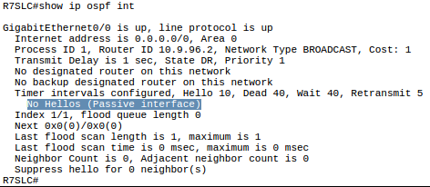
Config > OSPF int > OSPF neighbor > OSPF database > route OSPF
(this is order: enabled ospf on an interface, then they become neighbor rs, then exchange LSDB containing LSAs, then each use dijkstra's SPF to calculate routes)
(int > neigh > db > route)
# show ip ospf interface {brief} ! WILL SHOW WHO DR
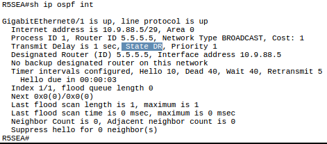
# show ip ospf neighbor ! lists all neighbors INCLUDING DR
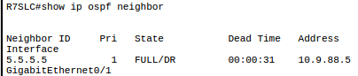
# show ip ospf database ! Lists contents of LSDB, here you can see the LSAs
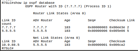
# show ip route {ospf} ! Notice if “O IA” meaning INTER-area, meaning route from to OSPF area
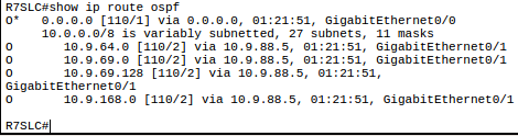
# show ip protocols
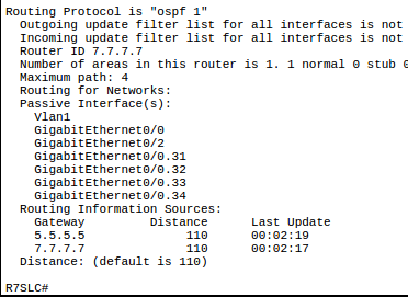
! RID:
if: configured by “R(config-router)# router-id {15.1.1.1}”
else: Highest active loopback int IP (ie largest IP of active Loopback ints. With int status code up/down or up/up status)
Else: Highest active int I
! “R# show ip ospf” to see RID
when two R try become neighbors, they go through the neighbor requirements.
to check, use
R# show ip ospf int
! to check hello and dead timers, same area, and authentication
also check if RIDs are unique with
R# show ip ospf
alternatively
R# debug ip ospf [hello | adj]
if multiple commands are telling an int to use different areas. Such as multiple network statements and an interface osf statement. The order of preference is:
Interface command (ip ospf 1 area 0),
then the first network statement (one closer to the top of the running-config)
finally any other statements.
EVEN IF ONE NETWORK STATEMENT IS MORE SPECIFIC, DOESN'T MATTER. THE FIRST ONE.
show ip ospf int
ospf-
Router w/ highest RID = DR
Router w/ 2nd highest RID = BDR
show ip ospf neighbor
FULL = full neighbor
show ip protocols
OSPF process ID
RID
nets advertized
neighbors
default admin distance
(for OSPF: 110)
show ip ospf
OSPF process ID
RID
OSPF SPF
OSPF area info
show ip ospf interface
list of OSPF-eabled ints
if 'Network' statements correct
show ip ospf interface brief
summary & status of OSPF ints
Open Shortest Path First
OSPF
Neighbor Table
Link State Database (LSD)
Routing Table
Neighbor Table:
used to store data about adjacent neighboring Routers
Use Hello messages to discovery OSPF routers, add their info to neighbor table (and to LSD)
Link State Database:
Database of all different networks in environments, and all possible paths to reach those networks.
Uses "Link State Advertizements" (LSAs) to to fill LSD
Run Shortest Path First Algorithm against LSD, which then populates the OSPF routes in the Routing Table.
__
For two Routers to become Neighbors:
must be directly connected
Same Subnet/Mask (AKA same network)
Hello-Interval & Dead-interval must match
(timers for OSPF)
Area ID (usually Area ID: Zero)
Authentication (is used)
Stub Area Flag
MTU Size must match
all connect to DR & BDR, if DR down than BDR becomes DR and new BDR is chosen.
If original DR comes online again, no change/aka original DR does not become DR again.
You would have to reset the new DR and BDR but that would cause interruptions.
chosen by higher"Router ID", if not ID than Address (?) and then by interfaces (even those not used)
Neighbor States
Down - no hello received
Init - Hello received, yet to respond
2-way - hello messages exchanged
ExStart - Master router/slave router selected
Exchange- Database descriptor packets exchanged, to build LSD
Loading - Link state requests/link state advertisements exchanged (when Net changes)
Full - once synced, Neighbor relationship established
LSA: Link State ad
LSA Type Function
1 Router Used to advertise Point to Point Nets
2 Network Used to advertise Ethernet Networks
3 Network Summary Used between areas
mote types as well
wild card mask = inverse of Subnet Mask
-------------
more ofps, that needs to be merged w/ main OSPF category
ospf
- IP protocol type 89
- R sends HELLOs containing R’s RID to 225.0.0.5 (all OSPF Rs multicast v4 add), and continue to do per Hello timer.
- SPF: “Dijkstra's Shortest Path First algorithm”; sum of all outgoing int costs (ignores incoming cost). If >1 route, chooses route w/ the best metric (lowest cost) to add to routing table. (depending on OSPF area design, cost calculation processes may differ)
- Hello Msgs: Messages containing RID. Occurs at frequency of Hello timer. Full state OSPF Neighbors send Hellos ever <hello timer interval> to maintain relationship.
- RID: “Router ID”; are 32-bit numbers (4x4x4x4; represented in decimal like IP addresses). Chosen by manual configuration (router-id x.x.x.x) or by copying an active interface’s IPv4 address.
- LSA: “Link-State Advertisement”; contains topology info. LSA creator refloods each LSA (that they created) every 30 mins (by default). If LSA changed (int go’s down), R modifies LSA & floods.
- LSDB: “Link-State Database”; Contains all LSAs for an area, & brief summary info for others. All Rs in area should have same LSDB (i.e. 1 LSDB per area). Use SPF w/ LSDB to generate OSPF routes.
- LSR: “Link-State Request”: Requests LSUs/LSAs. (can be sent in response to DD packets during LSDB exchange process)
- LSU: “Link-State Update”; Contains LSAs. (can be sent in response to LSRs)
- States: Status of OSPF neighbor relationship. Null > Init > 2-Way > ??? > Full.
- Null: Note aware of other
- Init: Received a Hello from a potential neighbor with acceptable parameters, and I will (or have) respond w/ Hello.
- 2-Way: “Adjacent”; I’ve been ack’ed (implying SATA checks all passed), and I’m now prepared to exchange LSDB DDs if needed. (this is the final state between two DROthers)
- ExStart/ Exchange / Loading: (not covered on CCNA) but are used in the process of syncing LSDBs / becoming full-state between DROthers and BRD & DR. (see “LSDB Sync Process”)
- Full: “Fully Adjacent”; LSDBs fully synced. OSPF Rs only become FULL-state w/ BDR & DR, all else are 2-way. Sends maintenance Hellos. (Full buds! Full of each other’s secrets)
- DD packet: “Database Description packet”; Effectively a checklist listing all LSAs within one’s LSDB.
- DR: “Designated Router”; 1 per area.
- BDR: “Backup Designated Router”; If DR fails, BDR takes over as the new DR (a DROther is then elected as the new BDR). 1 per area.
- DROther: “DR Other”; OSPF R that is neither a BDR nor a DR.
- Hello Timer: (AKA Hello Interval); How often send Hellos. Default = ?
- Dead Timer: (AKA Dead Interval); How many sequential Hello-intervals lacking a Hello from specific neighbor before neighbor is considered dead. Default: 4 * Hello-interval
- OSPF Neighbors:
- Topology change: When topology changes (e.g. int goes down/down), R that maintains the impacted LSA (the R that created the LSA) modifies the LSA and floods the new version.
- Becoming Neighbors:
- Similarity Requirements: “S.A.T.A.”
- Subnet
- Area
- Timers (Hello & Dead)
- Authentication (if applicable)
- Process:
- OSPF R sends multicasts Hello Msgs out all OSPF-active (not passive) ints to 224.0.0.5 (the All-OSPF-R v4 multicast add) (also listens on this add for others)
- When R receives an OSPF Hello, it checks the settings (SATA) in that hello to make sure they are compatible with own OSPF settings. If compatible: temporarily becomes “state: init neighbor” (even before replying).
- then R2 responds w/ Hello to R1, listing R2’s RID as seeing R1’s RID and R1’s OSPF settings. This lets R1 know that it’s first hello has been ack’ed, and from R2’s perspective R2 is ready to become full (2-way) neighbors! R11 goes from not neighbors, past the interim init state, directly to 2-way neighbors state.
- R1 sends the third and final Hello, so R2 can become (2-way) neighbor state also!
- then they are ready to exchange LSDBs.
- “2-way” state means 'ready for 2-way comms’ ready for 2-way communication (of LSDBs)
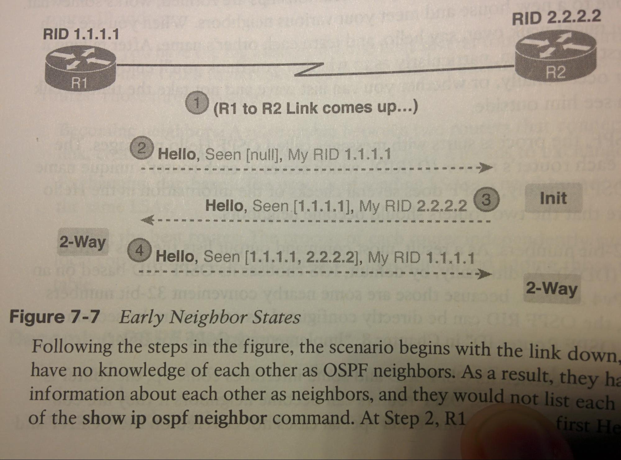
- LSDB Sync Process: (Syncing LSDBs between DROther and BDR/DR, to enter “FULL” OSPF neighbor-state). Exstart > Exchange > Loading > Full.
- R1 enters ExStart-state, and sends DD to R2. (effectively a checklist listing all LSAs within one’s LSDB.)
- R2 enters Exchange-state, and replies with R2’s DD.
- Rs enters Loading-state, and use LSRs (Link-State Requests) to request LSUs (Link-State Updates) containing the LSAs (Link-State Advertisements) each lacks.
- Rs, still in Loading-state, send Link-State Updates (LSUs) containing those Link-State Advertisements (LSAs) to sync LSDBs.
- Once fully synced, they both reach the FULLy adjacent STATE (“FULL State”)
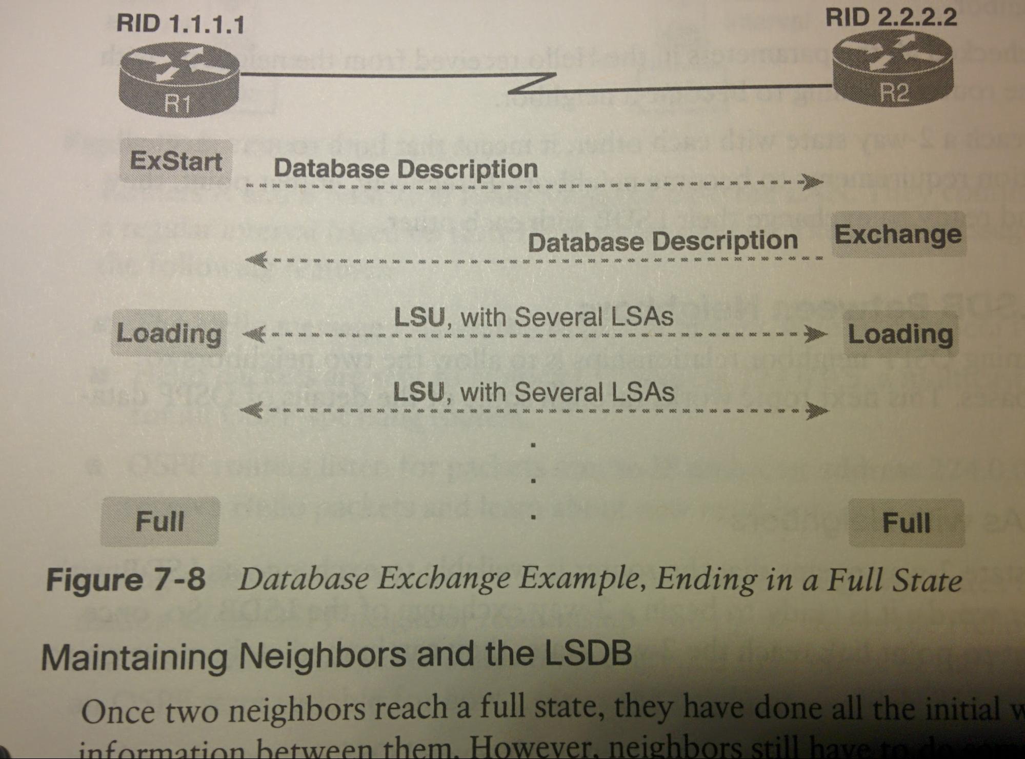
- Neighbor Maintenance: Maintenance done by FULL-state OSPF neighbors to maintain FULL-state.
- Send Hellos every <hello interval>. Dead timer by default (4 * Hello timer)
- Rs will reflood each individual LSA every (by default) 30 minutes after previously flooding that LSA, even if nothing has changed. (each LSA has individual timer for this)
- If topology change occurs, R will flood the updated LSA containing the newly changed info. (This new LSA is flooded by each R that receives it, and each R uses SPF to recalculate routes with the new info)
- Backbone Area: Area 0; all other areas must connect to the backbone area.
- ABR: “Area Border Router”; An OSPF router with at least 1 interface in Area
- Backbone Router: R connected to the backbone area (includes ABRs). A R with an interface in the backbone area.
- Internal Router: R in one area (not the backbone area), with all interfaces in the same (non-backbone) area.
- Area: A set of routers and links that shares the same LSDB information, but not with routers in other areas, for better efficiency. (~50 R network would benefit from using multiple areas)
- Area Rules:
- All ints connected to the same subnet should be in the same area
- Each area should be contiguous
- All non-backbone areas must use an ABR to connect to the backbone area (area 0).
- Issues with too-large areas: With large numbers of routers (e.g. 900) using a single OSPF area would greatly increase SPF calculation time on each R (CPU), increase latency for LSA/LSUs to travel entire network (convergence time) on each R, larger topology database increases RAM usage on each R, increased number of SPF recalculations due to larger network having larger number of things that can change (frequency of SPF recalculations; CPU).
- Backbone Area: A special OSPF area to which all other areas must connect - Area 0
- Intra-area route: A route to a subnet inside the same area as the router.
- Inter-area route: A route to a subnet in an area of which the router is not a part of.
224.0.0.5: All OSPF Rs
224.0.0.6: All OSPF DRs
OSPFv3: IPv6
do above first^
R(config)# ipv6 unicast-routing (this on Rs, do SDM on L3S'es)
R(config)# ipv6 router ospf [#]
ipv6 ospf, must do on the ints.
can check that it is there with Show run
and look for "ipv6 ospf [#] area [0]"
if not there, then go to int and put there
R(config-if)# ipv6 ospf [#] area [0]"
no ospf network cmds for OSPFv3.
ospfv3 is tweak to allow ipv6 on ints (not networks)
-
>^Then on each active int that you want OSPF...
>(passive int= no send ospf out this int, will advertize the int/net though)
>(passive int= will advertize the int to other NON-PASSIVES, but will not send hello msgs to this int. ie tell others of this but don't tell it of others)
-
>Router ID chosen like this...
>if: explicitly configured
>else: ipv4 loopback
>else: highest active ipv4 add
# show ipv6 route ospf
- FF02::5 All OSPF Rs v6 multicast
- FF02::6 All OSPF DRs v6 multicast
R(config)# ipv6 router ospf 10
R(config-router)# router-id 2.2.2.2 ! The RID may need to be different from the OSPFv2 RID, but this may or may not be true.
R(config-router)# auto-cost reference-bandwidth 1000
R(config)# interface G0/0
R(config-if)# bandwidth 1000000
R(config-if)# ipv6 ospf 10 area 0
EIGRP: Enhanced Interior Gateway Routing Protocol
- EIGRP: An example of IGP (interior gateway routing protocol): a protocol designed for use within 1 AS
- Metric: (((10^7 / least int BW) + cumulative delay) *256)d
(config)# router eigrp [1] #= AS# / Process ID #, must match on devs
(config-router)# eigrp router-id x.x.x.x
(config-router)# no auto-summary ! auto-summary automatically assumes classful subnetting; Only works on classful adds / non VLSM
(config-router)# network [10.0.10.0] [0.0.0.255] ! Net & WC to advertise
(config-router)# passive-interface F0/0 ! says IF "rtr# network ..." exists, don't form adj but adv (drops tx’ed and rx’ed eigrp hellos)
(config)# int g0/0
(config-if)# ip hello-interval eigrp [1] [5] ! AS#=1, 5=how often send hello in s. 5=default
(config-if)# ip hold-time eigrp [1] [15] ! AS=1, 15=long until no hello = dead? 15 default
(config)# int g0/1 ! send summary ad out this int; must do on all ints want to send to)
(config-if)# ip summary-address eigrp [1] [summary-add] [SubMask] ! this tells all devs across g0/1 that we have a route to summary-add.
(config-if)# bandwidth 512 (this would set bandwidth to 512Kb/s. This does not change the actual physical BW of the link, but tells IOS (& EIGRP by extension of IOS) what speed to assume it is using)
(config)# ip route 0.0.0.0 0.0.0.0 10.0.0.7 [1] ! 1 at end = manually setting the AD of this route
(config)# router eigrp 1
(config-router)# redistribute static
# show ip protocols | i redistributing static
# show ip route | i 0.0.0.0 (should be "D*EX"; D=DUAL, *=possible Default Route, ED=External EIGRP, AD = Admin distance of 170
# show ip eigrp neighbors ! lists EIGRP neighbors (ip, int, uptime)
# show ip route eigrp ! learned by D = learned by DUAL.Lists metric
# show ip eigrp topology ! TopDB w/ metrics
R# show ip protocols
! what nets adv
EIGRP sends occasional ‘EIGRP-Hello’ msgs to multicast 224.0.0.10 (and the IPv6 variant) to let others know that R is still up and running.
When two eigrp Rs try to form relationship and become neighbors, they must pass these steps
- can communicate ! show ip int brief && ping
- pass EIGRP auth ! debug eigrp packets
- same ASN ! show ip protocols
- same subnet used by ints ! Each int must be ‘directly connected’ to other int
- same K values ! show ip protocols
Then added to neighbor-table.
# show ip eigrp neighbors ! lists EIGRP neighbors (ip, int, uptime)
Once in neighbor table, neighbors exchange full-updates (containing all known routes; this is the only time full-updates are sent), by sending via RTP unicast if to one R, or RTP multicast 224.0.0.10 (or IPv6 variant) if more updating more than 1 R in subnet. that information is used to create the “Topology-table”.
# show ip eigrp topology ! TopDB w/ metrics
FInally each R uses their own “Topology-table” to calculate their lowest metric route to each learned subnet. The best ones are added to their “Routing-Table”.
# show ip route [eigrp?]
EIGRP update use ‘reliable transport protocol’ instead of TCP or UDP.
EIGRP only sends partial updates when something changes. And only full updates once, after becoming neighbors.
EIGRP sends ‘update’ messages when something in topology changes. these messages are sent to either: 1. the unicast address of 1 device 2. the multicast address of ‘224.0.0.10’. These updates are sent (not with TCP or UDP) but Reliable Transport Protocol (RTP), not to be confused with Real-time Transport Protocol (VoIP).
Full update = all known routes
Partial update = only info about recently changed routes
https://www.cisco.com/c/en/us/support/docs/ip/enhanced-interior-gateway-routing-protocol-eigrp/13681-eigrpfaq.html
EIGRPv6
(config)# ipv6 unicast-routing (this on Rs, do SDM on L3S'es)
(config)# router eigrp {2} (must be diff AS# then v4)
(config-rtr)# eigrp router-id {2.2.2.2}
(config-rtr)# passive-interface F0/0 (says IF "int# ipv6 eigrp 2" exists, don't form adj but adv
(config-rtr)# no shutdown (THIS IS REQUIRED FOR v6!)
(config)# int g0/0
(config-if)# ipv6 add FE80::1 link-local
(config-if)# ipv6 add 2001:ACAD::1/64
(config-if)# ipv6 eigrp 2 (2=AS#)
(config-if)# ipv6 hello-interval eigrp [1] [5] (AS#=1, 5=how often send hello in s. 5=default
(config-if)# ipv6 hold-time eigrp [1] [15] (AS=1, 15=long until no hello = dead? 15 default
(config-if)# ipv6 summary-address eigrp [1] [summary-add] [SubMask]
# show ipv6 eigrp neighbors lists EIGRP neighbors (ip, int, uptime)
# show ipv6 route eigrp learned by D = learned by DUAL.Lists metric
# show ipv6 eigrp topology TopDB w/ metrics
EIGRP: Configure Bandwidth that EIGRP can use
(config)# int s0/0/0
(config-if)# ip bandwidth-percent eigrp 1 50 ! (50=50% is max percentage of bandwidth that EIGRP can use)
EIGRP: Authentication w/ MD5
//uses a pre-shared key
//multiple keys can be configure
//IPv6 is same but use "ipv6" instead of "ip"
EIGRP: Create a Keychain & Key
R(config)# key chain {name-of-chain} //^Created key chain
R(config-keychain)# key {key-ID} //# used to ID key; best for Rs to use same #
R(config-keychain-key)# key-string {key-string-text} //keyString is the pre-shared key;ie password
EIGRP: Configure EIGRP auth using keychain & Key
//Do this on all EIGRP enabled ints
R(config)# int {G0/0}
R(config-if)# ip authentication mode eigrp [AS#] md5
R(config-if)# ip authentication key-chain eigrp [AS#] [name-of-chain]
____
Below info needs to be merged into the above main section:
EIGRP (ex proprietary protocol by Cisco)
Metric Calculation:
*Bandwidth Configured
*Delay of Line Configured
Reliability Measured
Load - Measured
* = Default
Measured Values are bad because then you as NetSpec Do not know exactly how your Network is operating.
BGP: Border Gateway Protocol
- BGP is an example of EGP (Exterior Gateway Routing Protocol): A protocol designed for use between different AS’s.
- ! “ASN” = Autonomous System Number
- ! ‘NLRI’s : Network Layer Reachability Information : contain prefix/length information + PA . (Path attributes) (usually sent between BGP peers via ‘update’ msgs
R(config)# router bgp {AS#} ! enables BGP, defines AS# to use
R(config-router)# bgp router-id {RID} ! Just like OSPF, if not manually defined uses largest active loopback add, else uses largest active int add.
R(config-router)# neighbor {ip} remote-as {AS#} ! add neighbors; enter info of peer)
R(config-router)# neighbor {ip} update-source {Loopback0} ! use a loopback int because: if multiple links between this R and neighbor, will load-balance + redundancy, also
R(config-router)# neighbor {ip} ebgp-multihop {1} ! Think this is required when using ‘update-source Loopback#’ since eBGP usually requires hop-count 0 (aka directly connected) this cmd changes that.
R(config-router)# neighbor {ip} password {pass123} ! Optional, but adds MD5 authentication.
R(config-router)# neighbor {ip} shutdown ! Puts neighbor relationship into “Administratively down / Idle”. Idle if looking at ‘show ip bgp summary’
R(config-router)# network {net-add} mask {sub} ! internal nets to adv, list all nets in AS, not just directly connected)
! (this commands adds the NLRI, which contains prefix/length info + PA, to its BGP table if there is an exact same match in the IP routing table)
! omitting ‘mak {sub}’ causes IOS to assume classful addressing. Explicit > implicit, therefore avoid this.
(share these routes via internal routing protocol e.g. OSPF [default-information originate], EIGRP)
R# show ip route
R# show ip bgp
R# show ip bgp summary ! This also lists neighbors/peers.
!In “State/PfxRcd” column of peers:
‘idle’=shutdown/waiting to retry,
‘connect’=attempting but not completed,
’Active’=tcpComplete but no BGP msgs,
‘Opensent’=tcp complete and we sent BGP open msgs, we sent first message used to create BGP neighborship
‘Openconfirm’= TCP complete, received BGP-open message attempting to build neighborship
‘Established’= Rs are now neighbors/peers, and can exchange BGP update msgs.
R# show ip bgp neighbors
Is Exterior gateway Protocol; for routing between AS's
Advertises ‘network prefixes’ and prefix length (like summarized routes) (formally ‘NLRI’s : Network Layer Reachability Information) and instead of individual subnets. I.e. route summarization.
BGP uses ‘route attributes’ in comparison to a single metric.
Uses ‘update’ messages to send “NLRI”s to peers (which contain prefix/length info) and “PA”s (Path Attributes)
TCP port 179 used to share BGP info
two types; Internal BGP (iBGP ; used between R's in same AS) & External BGP (eBGP) for inter-AS.
Never use BGP when only one route out of AS(use static default route), or when limited knowledge of BGP since misconfigurations can impact entire internet
Ways BGP is implemented:
Default route only
ISPs send only default route to org, sub optimal routing if org uses ISP 1 as default route but destination net is on ISP2
Default route & ISP routes
^Like default route but ISP also adv their nets
All internet routes
ISP adv routes and metrics to both their AS nets AND OUTSIDE NETS; always optimal routing but adds >600,000 routes to
(BGP Home Terminology)
How many redundant connections (to each ISP) | How many different ISPS
|
Links/ISP |
1 ISP |
Multiple ISPs |
|
1 link |
Single Homed |
Single Multihomed |
|
2 links |
Dual Homed |
Dual Multihomed |
|
3 links |
Triple Homed |
Triple Multihomed |
ACLs: Access Control Lists
- SQ# = Sequence Number
- ACE:
- Access Control Entry; A single statement/rule within an ACL. For example: permit 1.1.1.1
- Remark: Remarks are just text for understanding, and have no effect on operation. Use for documentation of why you are adding an ACE. Configured like an ACE.
- RACL: Router Access Control List
- Outbound ACLs are not applied to packets that the same R creates. (i.e. if R1 has an ACL that blocks all outbound traffic on R1’s g1/0/1, but the router itself creates a packet destined out that int, that packet will be sent. e.g. GRE Tunnels)
- ACLs can be applied either inbound/ingress (Rx) before the R makes it forwarding/routing decision, or outbound/egress (Tx) after the R makes it forwarding/routing decision.
- Packets are matched to the first rule that it matches, not the most specific.
(e.g. “access-list 1 permit 1.0.0.0 0.255.255.255” “access-list 2 deny 1.1.1.0 0.0.0.255” then a packet with add 1.1.1.1 came, it would match the first one before even reaching the 2nd)
- ACL names cannot begin with a number. Best to use a capital letter.
- Best Practise:
- Place more specific statements early in the ACL
- Begin ACL names with a capital letter.
- ACL Application:
- access-group: Is used to apply an ACL to an int.
- access-class: Is used to apply an ACL to a line (e.g. vty or con).
- access-list: Is used to create an ACL, rather than apply it.
- Order of ACL operation:
- ingress PACL
- ingress VLAM (VLAN access-map)
- ingress ‘Cisco IOS’ ACL (only if a L3 dev)
- egress ‘Cisco IOS’ ACL (only if a L3 dev)
- egress VLAM (VLAN access-map)
There are different types of ACLs. They be standard or extended, and each may be either numbered or named.
|
|
Extended: Matching -Source & Dest. IP -Source & Dest. Port -Others |
Standard: Matching -Source IP |
|
Named: -ID with Name -Subcommands |
Extended Named |
Standard Named |
|
Numbered: -ID with Number -Global Commands |
Extended Numbered |
Standard Numbered |
- Wildcard Mask: in binary, if it is a 1, it is treated as a wildcard. If it is a 0, it is not treated as a wildcard.
- Example 1: 0.0.0.0 would mean there are no bits that are treated as wildcards, and as such, would need to match the exact IP add. There is only 1 possible match.
- Example 2: 0.0.255.255 would mean there that the last 16 bits are treated as wildcards, and as such, only the first 16 bits of an IP address would need to be the same to match, while the last 16 would always match.
- Example 3: 255.255.255.255 would mean that all bits are treated as wildcards, and as such, would match anything and everything.
# show access-lists ! will show both IPv4 ACLs and IPv6 ACLs
# show ip access-lists ! will show only IPv4 ACLs (because “ip” is IPv4 and “ipv6” is IPv6).
# show ip interface g1/0/1 ! you will see “outgoing access list is x” and “inbound access list is x”.
R(config)# access-list … log ! “log” will generate syslog msgs occasionally, w/ something like “Feb 4 18:30:24.082: %SEC-6-IPACCESSLOGNP: list 7 permitted 0 10.2.2.1 -> 10.2.9.9, 1 packet”
eq = equals
neq = not equal to
lt = less than
gt = greater than
range = range (x to y ?)
ACL: Extended Named
R(config)# ip access-list extended aclname
R(config-ext-nacl)# [sq#] permit [tcp|udp] source wc dest wc [eq|neq|lt|gt] [port] [established] (log)
! if tcp or udp, can also match against ports by appending something like “eq 80”. (ios will recognise and convert some. e.g. 80 to www). see below for those and “established” in reflexive acl. you can put these after both the source wc and also after the dest wc.
R(config-ext-nacl)# [sq#] deny ip any any
ACL: Extended numbered
Place standard ACLs as close to the source as possible to conserve bandwidth, this is in contrast to standard acls (which should be as close to the dest as possible because they cannot filter the dest).
R(config)# ip access-list extended {name}
R(config)# access-list {100-199 | 2000 - 2699} permit [tcp] source wc dest wc eq [port] [established] (log) ! if tcp or udp, can also match against ports by appending something like “eq 80”. (ios will recognise and convert some. e.g. 80 to www). see below for those and “established” in reflexive acl. you can put these after both the source wc and also after the dest wc.
R(config)# access-list {100-199 | 2000-2699} permit udp host 10.1.1.1 {dest} {wc} ! extended acls must use host keyword when specifying /0 wc, in comparison to standard acls which may just list the ip (w/o “host”)
R(config)# access-list {100-199 | 2000-2699} deny ip any any
R(config-if)# ip access-group {acl-name/num}
ACL: Standard Named
- 3 benefits. Names are easier to remember, uses acl subcmds rather than global cmds, and allows editing via sequence numbers.
R(config)# ip access-list standard aclname ! note: we now use “ip access-list …”, with “ip”.
R(config-ext-nacl)# [sq#] permit 1.1.1.1
R(config-ext-nacl)# [sq#] permit 2.2.2.2
R(config-ext-nacl)# [sq#] deny any [log]
R# show access-list ! shows sequence numbers
R(config-ext-nacl)# no sequence# ! removes an acl entry (e.g. no 30)
ACL: Standard numbered
- Standard ACLs only check the source IP address.
- Because of ^, standard ACLs should be placed as close to the destination as possible (egressing the int to the dest), to avoid dropping packets from the source that are actually intended for a different dest.
- ACL entries are entered sequentially. I.e. they are evaluated as they were entered in time. I.e. the first cmd is evaluated first, then the 2nd cmd entered is evaluated 2nd.
- Numbered ACLs can actually be inputted like named ACLs (in that you use “ip access-list standard [name/num]” to enter into access-list config mode and use subcmds.) However IOS will save it in running-config like a numbered acl, with global cmds.
R(config)# access-list {1-99 | 1300-1999} {permit | deny} 10.1.1.1 [wildcard] ! If you do not specify a wildcard mask, it is treated as “0.0.0.0”. i.e. the entry would only match that specific IP add.
R(config)# access-list {1-99 | 1300-1999} permit [add] [wildcard]
R(config)# access-list {1-99 | 1300-1999} remark blah blah blah ! notes
R(config)# access-list {1-99 | 1300-1999} deny any [log] ! This is redundant, but allows you to see the packet match counter via show cmds (while the implicit version of this does not).
R(config)# int {g1/0/1}
R(config-if)# ip access-group {acl-name/num} {in | out} ! This applies the already created ACL (either a named or numbered) to this particular interface, and in the specified direction.
MACL: MAC ACL
- https://www.cisco.com/c/m/en_us/techdoc/dc/reference/cli/n5k/commands/mac-access-list.html
- Definition:
- MAC ACLs are created with the “mac access-list” cmd. This is in contrast to the L3 IP access-lists, which are created with the “ip access-list” cmd.
- Benefits:
- MAC ACLs are useful when attempting to filter traffic that is non-IP traffic.
- Operations:
- Implicit Deny:
- There is an implicit “deny any any protocol” ACE at the end of every mac access-list.
- Because of this, typically mac access-lists will explicitly end with a “permit any any” ACE so that one is able to see how many times that ACE is matched/hit.
- Filters based on ethernet frame fields of unsupported type frames (i.e. frames that are not IP, not ARP, and not MPLS)
- A MAC access list is not applied to IP, MPLS, or ARP messages
- For how to apply a MAC ACL to a L2 int, see PACL.
- Mac access-list s can only be applied to ints in (i.e. inward/ingress). They can not be applied egress.
|
! MAC ACL CREATION (config)# mac access-list extended macl-name (config-ext-macl)# {permit|deny} host [sourceMac | any] [destMac | any] (config-ext-macl)# {permit|deny} any any ! Explicit “any any” cmds are typically appended to all ACLs.
! VERIFICATION # show [mac] access-lists |
PACL
- https://www.youtube.com/watch?v=L0vmJL0WuIQ
- https://www.cisco.com/c/en/us/td/docs/switches/lan/catalyst6500/ios/12-2SY/configuration/guide/sy_swcg/port_acls.html
- Definition:
- “Port Access Control Lists” / “L2 port ACLs”.
- PACLs filter ingress traffic (L2 and/or L3) on L2 ints. (This is in contrast to ACLs which are applied to L3 ints, including SVIs.)
- Types:
- IP PACLs
- filters by IPv4 / IPv6 qualities.
- Can be either named or numbered, standard or extended.
- These are the same IP access-lists that can be applied to L3 ints (the same IP ACL can even be applied to L2 and L3 ints at the same time).
- preferably a (named) extended IP access list, but can also use a standard IP access list.
- MAC PACLs (named and extended)
- See MAC ACL.
- Modes: interaction with other access-lists
- Configured with the “access-group mode” cmd.
- ‘Merge’ mode
- (The default) PACLs, VACLs, & standard ACLs are combined into 1 ingress filter.
- Merge mode works only on access ints (i.e. it can not be applied to trunks)
- ‘Prefer Port’ mode
- PACLs override effects of other ACLs (Cisco IOS ACLs and VACLs).
- Unless a hardware forwarding exception is encountered and software forwarding is used. In which case the route processor applies the ingress Cisco IOS ACL regardless of PACL mode. (This can occur if packets are egress bridged (due to logging or features such as NAT), or packets have IP options.)
- Works on both access and trunk ints.
- Operation:
- PACLs (regardless of type) only filter ingress traffic, not egress.
- Gotchyas:
- There can be only 1 type (e.g. extended IP access-group, MAC extended access-group) per direction (e.g. ingress, egress) per int. If another is applied, it will overwrite the existing one.
- There can be at most one IP access list and one MAC access list applied to the same Layer 2 interface per direction.
- PACLs do not filter any ingress L2 control plane traffic (e.g. CDP, VTP, DTP, STP)
- PACLs are not applied to MPLS or ARP messages.
- PACLs cannot filter Physical Link Protocols and Logical Link Protocols, such as CDP, VTP, DTP, PAgP, UDLD, and STP, because the protocols are redirected to the RP before the ACL takes effect.
- Can be configured on a L2 port-channel int, but not on the individual ints.
- Compatibility:
- Different IOS’ support PACLs in different amounts. Some may support some PACL features, others all, others none.
|
! IP PACL ! (config-if)# access-group mode {merge | prefer port} (config-if)# ip access-group aclName in ! This applies an existing (preferably named-extended) access-list to a L2 int, making it an IP PACL.
! MAC ACL (MAC ACL becoming a MAC PACL) (config-if)# access-group mode {merge | prefer port} (config-if)# mac access-group aclName in ! This applies an existing (named-extended) mac access-list to a L2 int, making it a (named-extended) MAC PACL.
! VERIFICATION # show access-list |
VLAM: VLAN Access Map / VACL
- VLAM/VAM: “VLAN Access-Map”.
- Definition:
- A VLAN Access-map is an access-map (similar, but different, to ACLs) applied to an entire VLAN (all of the ports, including future ports added to the vlan in the future).
- Called “VLAN access-maps” because that’s the cmd used to create them, and they follow the same logic of route maps (in contrast to ACLs).
- Sometimes colloquial/incorrectly referred to as VACLs or VLAN ACLs.
- with certain limitations, filters L2 and/or L3 traffic within a VLAN.
- Operation:
- Sequence# absence:
- if sequence# is omitted, one will automatically be assigned.
- Typically the first one is 10, and each additional one is incremented by 10. E.g. 10, 20, 30, etc.
- Match statement absence:
- If a sequence# within a VACL does not have a match statement, then everything will match it.
- Typically the final entry (i.e. highest sequence#) in a VLAM is a “action forward” with no match statement.
- ACL permits:
- VLAMs use ACLs, both IP and MAC, to match datagrams for the VLAM. Those ACLs must use “permit” ACEs to match datagrams for the VLAM, and “deny” ACEs for those not to match. Those ACLs are only for identifying datagrams for the VLAM.
- I.e. think “permit” = ‘match’. or “permit” = ‘permitted to be matched for the VLAM’
- 1 VLAM per VLAN:
- A VLAN may use only 1 VLAM.
- A VLAM can be applied to multiple VLANs.
- Implicit Deny:
- There is an implicit (i.e. invisible) deny any any statement appended to all VLAN access-maps. I.e. if a datagram does not match any of the statements in a vlan access-map, it will implicitly be denied/dropped.
- VLAN access-maps typically have the last sequence entry be a “action forward”, and no match statement (to match everything).
- Else if it was a deny (e.g. like in the implicit deny any any), it would kill things like ARP.
|
! VLAM !
! create a mac/L2 access list. See MAC ACL (config)# mac access-list extended mac-acl-name (config-ext-macl)# permit host [sourceMac | any] [destMac | any]
! create a ip/L3 access list. See ACL: Extended Named (config)# ip access-list extended ip-acl-name (config-ext-nacl)# permit [protocol] [sourceIp | any] [destIp | any]
! create a VLAM which uses the mac and IP access lists. (config)# vlan access-map vlam-name [sq#] (config-access-map)# action {forward [capture] | drop | redirect int} [log] (config-access-map)# match mac address mac-acl-name (config-access-map)# match ip address ip-acl-name (config)# vlan access-map vlam-name [sq# +10] (config-access-map)# action forward
! Apply the created VLAM to the desired VLAN(s) (config)# vlan filter vlam-name vlan-list 2-10 |
! protocol is typically IP.
! If a datagram matches any of the match statements for this sequence, this action will be taken to said datagram.
! Create a new sequence in the VLAM, the datagram will be evaluated against this after all lower sequenced entries. ! if no match statements, everything matches. Here we drop all traffic (that did not match the above sequence).
|
ACL: IPv6
- IPv6 ACL Differences: Compared to IPv4 ACLs, they do not use wildcard masks, but rather use prefix length.
R(config-if)# ipv6 traffic-filter {acl-name/num} {in | out} ! Use this, after creating the ipv6 acl, to apply it to the specified interface.
Reflexive ACL
(https://drive.google.com/file/d/0BzTH5IWRQhLYblpPei04VmlOaWM/view)
- These ACLs exist on edge routers/firewalls. If external devs needs uninitiated access to a part of your internal network (e.g. DNS, or email), may be best to place reflexive ACL on internal int. Else, for better security, place the ACL on an access-link that connects your edge device to an unsecure/external device/network.
- Basic ACLs (not reflexive) can use the “established” keyword to filter tcp traffic based on whether the TCP ACK or TCP RST bits are set (because those indicate not the first in a session). And only worked with TCP (not UDP/others).
- Reflexive acls are better because they also check source & dest, not just TCP ACK or TCP RST bits, and also use temporary entries that expire, compared to basic acls that do not. (better security)
- For example: An internal dev sends a TCP SYN packet outside of your network. R will add a temporary ACL entry for that session to be allowed until the timeout period is reached (no matter the protocol), or 5s after 2 set FIN bits are detected, or immediately after matching a TCP packet with the RST bit set. (A set RST bit indicates an abrupt session closure).
- Reflexive acls do not have the implicit deny any any.
- Temporary ACL entries: Always permits, specifies same protocol (e.g. TCP), same source & dest (but swapped since external dev needs to be let in), if TCP or UDP (since other don’t use ports) then same source & dest ports (also swapped), and will expire either after timeout period (all protocols), or 5s after 2 set FIN bits are detected, or immediately after matching a TCP packet with the RST bit set. (A set RST bit indicates an abrupt session closure).
(config)# ip access-list extended [TxFilter] ! Create acl named “TxFilter”.
(config-ext-nacp)# permit tcp any any reflect TcpTxTraffic [timeout seconds] ! Any traffic matching this rule (ie tcp) will be temporarily added to the “TcpTxTraffic” list. You can specify for how long w/ “timeout”.
(config-ext-nacp)# permit udp any any reflect UdpTxTraffic [timeout seconds] ! Any traffic matching this rule (ie udp) will be temporarily added to the “UdpTxTraffic” list. You can specify for how long w/ “timeout”. ! You could replace the above 2 rules with “permit ip any any reflect Xtraffic”, but this would also include traffic types ICMP, EIGRP, GRE, etc.
! You could also replace the two separate UdpTxTraffic and TcpTxTraffic, with a single TxTraffic, and not have to have two separate “eval” cmds.
! You can also append (not prepend cuz prepend could match before being reflected) other Tx rules for ICMP, EIGRP, GRE, etc.
(config)# ip access-list extended {RxFilter} ! create acl named RxFilter
(config-ext-nacp)# evaluate TcpTxTraffic ! Anything in “TcpTxTraffic” will be matched. This is nesting the above ACL into this ACL.
(config-ext-nacp)# evaluate UdpTxTraffic ! Anything in “UdpTxTraffic” will be matched. This is nesting the above ACL into this ACL.
(config)# int [internet-facing-int]
(config-if)# ip access-group RxFilter in ! apply "TxFilter" to egress traffic
(config-if)# ip access-group TxFilter out ! apply "RxFilter" to ingress traffic
(config)# ip reflexive-list timeout seconds ! Default is 300s. This will apply to each reflection that does not manually specify its own timeout value.
# show access-list ! This will only show the TcpTxTraffic & UdpTxTraffic acls, but only if they have entries in them. Else, if empty, they will not be listed via this show cmd.
! If you are configuring reflexive access lists for an internal interface, the extended named IP access list should be one that is applied to inbound traffic. Furthermore, in this situation, you may also flip the names for “RxFilter” and “TxFilter”
- In Reality, instead of having two separate “permit tcp … TcpTxtraffic” “permit udp… UdpTxTraffic” cmds, they could both reflect to the same reflexive acl. “permit tcp … TxUdpTcp” “permit udp … TxUdpTcp”.
routing protocols exceptions
allow these if needed
ripv2: 224.0.0.9 UDP (port 520)
OSPF: 224.0.0.5 & 224.0.0.6 ospf
EIGRP:224.0.0.10 eigrp
R(config)# ip access-list extended aclname ! note: we now use “ip access-list …”, with “ip”.
R(config-ext-nacl)# [sq#] permit icmp any any echo-reply ! allows ICMP echo-reply msgs (not echo requests)
access-list 12 permit udp any any eq domain ! DNS
access-list 12 permit udp any eq domain any ! DNS
access-list 12 permit tcp any any eq domain ! DNS
access-list 12 permit tcp any eq domain any ! DNS
access-list 12 permit udp any any eq rip ! To permit Routing Information Protocol “RIP”
access-list 12 permit igrp any any ! To permit Interior Gateway Routing Protocol “IGRP”
access-list 12 permit eigrp any any ! To permit Enhanced IGRP “EIGRP”
access-list 12 permit ospf any any ! To permit Open Shortest Path First “OSPF”
access-list 12 permit tcp any any eq 179 ! To permit Border Gateway Protocol “BGP”
access-list 12 permit tcp any eq 179 any
R(config-ext-nacl)# [sq#] permit 2.2.2.2
R(config-ext-nacl)# [sq#] deny any [log]
R# show access-list ! shows sequence numbers
(ACl: Troubleshooting)
show ip access-list
show access-list
show interfaces
show ip interfaces
! “self-pings” are pings out and in your own int. that won’t test outbound acls (since the own dev created it) but it will test inbound acls. on serial ints, it will actually be transmitted across the medium.
________
<Applying ACLs>
line vty 0 15
access-class 10 in
int g0/0
ip access-group {number | name} {in|out}
</Applying ACLs>
NAT : Network Address Translation
show ip nat translate
Changing the destination address can be an option if you are expecting many incoming connections, and want to distribute the load across multiple sources. (have 2 servers serving the same thing, and load balance beween then)
inside-global inside-local outside-global outside-local
global = from perspective of the globe
local = from perspective of within our local network
inside = to our inside interface
outside = to the outside interface
inside-global = our inside interface/net from the perspective of the globe.
inside-local = out inside interface/net from the perspective of within our net.
outside-global =
outside-local =
NAT [fromDoingLab]
can do either "prefix-length 24" or "netmask 255.255.255.0"
(NAT: static)
R1(config)# ip nat pool [NAT-R1] 10.65.111.10 10.65.111.14 netmask 255.255.255.0
(^make pool of outside adds)
R1(config)# access-list [1] permit [172.16.0.0] [0.0.255.255] *******
(^make ACL of inside adds)
R1(config)#interface serial 0/0/0 *******
R1(config-if)#ip nat outside *******
R1(config-if)#interface fa0/0 *******
R1(config-if)#ip nat inside *******
R1(config)#ip nat inside source [list 1] pool [NAT-R1]
(^apply NAT; turn [these] into [these])
(^apply NAT; turn [ACL] into [pool])
(think pool as pool of available global adds)
>^NAT now implemented for packets permitted through ACL 1, and received...
>... on the inside int. The packets get translated to an address from [pool NAT-R1]
(PAT; convert from NAT)
acl stays same
nat inside and outside stay same
but the nat pool and the command to enable NAT are REMOVED!
R1(config)# no ip nat pool [NAT-R1] 10.65.111.10 10.65.111.14
R1(config)# no ip nat inside source list 1 pool NAT-R1
R1(config)# ip nat inside source [list 1] interface serial 0/0/0 overload ********
^[list 1] = acl #
PAT: Port Address Translation - from scratch
int g0/0
ip nat inside
int g0/1
ip nat outside
R1(config)# ip access-list standard NAT_THESE_ADS
permit 192.168.1.0 0.0.0.255
deny any
exit
ip nat inside source list NAT_THESE_ADS int g0/1 overload
(^
NAT?
R(config)# ip nat pool [PoolName] [startAdd] [endAdd] prefix-length 24
R(config)# ip nat pool [PoolName] 10.65.111.15 10.65.111.19 prefix-length 24
R(config)# access-list 1 permit 172.16.0.0 0.0.255.255
R(config)#interface serial 0/0/0
R(config-if)#ip nat outside
-
R(config-if)#interface fa0/0
R(config-if)#ip nat inside
R(config)#ip nat inside source list 1 pool NAT-R1
-
R# show ip nat translation
R# show ip nat translation verbose
# ^Will show when entry created & when used.
R# clear ip nat statistics
R# show ip nat statistics
R(config)#no ip nat inside source list 1 pool NAT-R1
R(config)#no ip nat pool NAT-R1 10.65.111.10 10.65.111.14
R(config)# ip nat inside source list 1 interface serial 0/0/0 overload
R?# show ip nat translation
# default translation timeout: 24hrs. Can change with...
R2(config)# ip nat translation timeout [s]
# to clear all dynamic translations before translation timeout...
R2# clear ip nat translation *
# to clear specific dynamic translation before translation timeout...
# can also specify last part i.e. outside local+global
R2# clear ip nat translation inside [global-ip] [local-ip] (outside [local-ip] [global-ip])
# to clear extended dynamic translation entry...
# last part is optional ()
R2# clear ip nat translation [protocol] inside [global-ip] [global-port] [local-ip] [local port] (outside [local-ip] [local port] [global-ip] [global-port])
NAT Static Setup
R(config)# ip nat inside source static [IL IP] [IG IP]
R(config)# int [IL int]
R(config-if)# ip nat inside
R(config)# int [IG int]
R(config-if)# ip nat outside
(NAT Static removal)
R(config)# no ip nat inside source static [IL add] [IG add]
or
R(config)# no ip nat inside source static
NAT Dynamic Setup
# 1. Define a pool fo global addresses to be used for translation.
# 2. Configure a standard acl permitting the addresses that should be translated.
# 3. Establish dynamic source translation, specifying acl & pool defined in prior steps.
# 4. Identify inside int.
# 5. Identify outside int.
R2(config)# ip nat pool [pool-name] [start-ip] [end-ip] netmask [netmask]
R2(config)# access-list [ACL#] permit [source] [wildCard]
R2(config)# ip nat inside source list [ACL#] pool [pool name]
R2(config)# int [type number]
R2(config-if)# ip nat inside
R2(config)# int [type number]
R2(config-if)# ip nat outside
IP SLA: Service Level Agreement (and tracking)
IP Service Level Agreement
IOS feature that allows analysis of IP service levels.
used to measure network performance
measures: jitter, latency, packet loss, etc
accessed w/ either CLI or SNMP
- Responder:
- Some IP SLA types require that the other end be configured as a IP SLA “responder”, while other IP SLAs (such as ICMP Echo) do not.
- Responders are Cisco IOS devs that support the IP SLA control protocol, and use the Cisco IOS IP SLA Control Protocol for notification, configuration, and on which port to listen and respond.
- (config)# ip sla responder” ! Enables Txing & Rxing IP SLA control packets.
- (config)# ip sla responder udp-echo ipaddress 172.16.99.` port 5000
(how configure IP SLA ICMP Echo operation)
|
R# show ip sla application ! (lists supported operation types, verify that icmpEcho is supported) R(config)# ip sla [sla#] R(config-ip-sla)# icmp-echo [destIp] [ source-ip x.x.x.x | source-interface g0/0 ] R(config-ip-sla-echo)# frequency 60 ! (optional; set rate that operation repeats in seconds; default=60) R(config)# ip sla schedule [sla#] start-time now life forever ! (e.g. [sla#]; optional ... ... "start-time now" starts right away other: "after hh:mm:ss" ... "hh:mm:ss <dayOfMonth>" to set exact time to start; dayOfMonth null = assumes this month month ... "pending" = does not start until start time is manually specified "life <forever>" last forever, or specify exact # of seconds; defaults 3600 s i.e. 1hr ) optional: "recurring" auto runs every day) R(config)# no ip sla schedule [sla#] ! (stops sla operation from occurring anymore)
R# show ip sla configuration [sla#] ! Verify correct parameters R# show ip sla statistics [sla#] ! Shows stats of operations
R# show ip sla application ! Returns the types of IP SLAs that are available.
|
Tracking
There are at least 2 kinds of tracking: Interface tracking and object tracking.
Note: HSRP can use its own interface tracking. See HSRP.
|
! Interface tracking (config)# track {track#} int [g0/1] line-protocol ! This creates a tracker which tracks said int.
! OBJECT TRACKING (config)# track {track#} ip sla {sla#} ! This creates a tracker which tracks sla#. There are most likely more items to track besides ‘ip slas’. (config)# track {track#} ? |
SNMP: Simple Network Management Protocol
- SNMP: “Simple Network Management Protocol”; L7 (Application); Many IP devices have commonalities which can be structured into a database & collected & analyzed by mgmt software. Allows one to have Centralized management station to ask all devices what current state is, stuff like what is fan temp, how much ram available etc
- SNMP Manager: “SNMP MGR”; Runs SNMP Manager software (e.g. Cisco Prime, Cisco Works, SolarWinds Orion) and uses “SNMP protocol” to manage “SNMP Agents” (e.g. A router/switch/server).
- NMS: “Network Management Station”; Another name for SNMP MGR. Net Admins can set NMS to notify if certain thresholds are met. Can analyze info over time (averages, etc).
- NE: “Network Elements”; (e.g. R, S, server) that run SNMP agent software. AKA a managed node.
- SNMP Agents: SNMP Agent software ran on managed nodes (AKA NEs, e.g. Router/switch/server). 1 per managed node. Is aware of all variables (OIDs) on that node/dev & stores them in its own MIB.
- MIB: “Management Information Base”; a hierarchical database of all OIDs (MIB variables) on that dev, both common & unique to that dev (a R may have ~7000 OIDs). R & S may share some, but not all OIDs. Organized into a hierarchy by RFC standards & vendor proprietary variables, & usually shown as a tree.
- OID: “Object ID”; MIB variables. Can be referenced in the MIB by either position (e.g. ISO[1] > org[3] > … > Interface[2]) or by number (e.g. 1.3.6.1.4.1.9.2.2).
- Server/Cx: The SNMP Agent is the server, and the SNMP Mgr is the client requesting info from the server. This is why the cmds to configure Agent are “snmp-server *”.
- Message Types:
- Get Msgs: NMS uses (UDP 161) “Get” request messages (‘Get msgs’) to poll/request info from Agents. NMS sends some form of a “Get request”, Agent responds with “Get Response”.
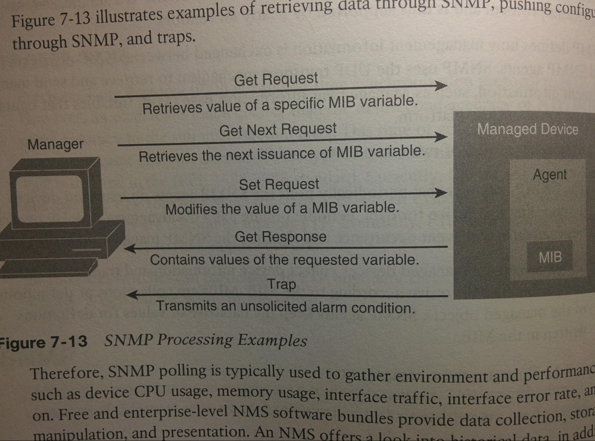
- Get-request: NMS requests a MIB OID.
- GetNext-request: NMS requests the next MIB OID.
- GetBulk-request: MGR requests multiple MIB OIDs.
- Get-Response: Txed from Agent to MGR in response to a MGR’s “Get Request”, contains the MIB values requested by the MGR.
- Set Msgs: NMS uses (UDP 161) “Set” msgs to set variables in the MIB of Agents, used as a way to configure devices. change info/config or perform actions (reboot Tx/Rx config file)
- Notifications: (UDP 162) Agents initiate msgs to NMS using “Traps” & “Informs” to tell of MIB OIDs passing defined thresholds (e.g. failed login attempt). In contrast to waiting for NMS polling the MIB w/ Gets.
- Traps: E.g. If configured, if G0/0 go’s down on an NE, the Agent will immediately Tx an SNMP Trap msg (UDP) to the NMS. (no confirmation that is arrives). Available since SNMPv1.
- Informs: Like Traps, still UDP but w/ L7 Application Layer reliability overhead, that is, if the NMS does not acknowledge receipt the Inform, Agent will continue to send. Added in v2.
- Poll: The action when an SNMP MGR sends a Get request to an SNMP Agent. Compared to Traps & Informs, there can exist a delay between when an event occurs and when it’s detected.
- Notification Community: “NC”; Preshared, plain-text, string used to authenticate an Agent sending Informs/Traps to Mgr. Where cStrings auth the Mgr, Notification Communities auth the Agent.
- Community Strings: ‘CStrings’; Defined in v1 & v2c, are pre-shared clear-text strings sent w/ each Get/Set msg from NMSs to Agents. If present, agent processes the requesting msg, else dropped.
- RO Communities: Read-Only CStrings. Allowing only “Get” msgs (not Set msgs).
- RW Communities: Read-Write CStrings. Allowing both “Get” and “Set” msgs. This is a plaintext password that has exec permissions! If no RW community present, all Set request msgs are dropped.
- Config: SNMP is disabled by default until the first “snmp-server” cmd is entered into global config mode (there is not snmp mode, all are global cmds) and is disabled when all “snmp-server *” cmds are removed, which can be done with “no snmp-server”. SNMP Agents act as the Server to their MIB, and the SNMP Mgr acts as the client requesting info from the server, this is why the cmds to configure the Agent are “snmp-server *”.
- Best Practise:
- Use SNMPv3 authPriv
- Use extended ACLs to limit SNMP comms to only known/trusted SNMP MGRs & Agents (both ipv4 and ipv6).
- use SNMP views to limit views of the MIB to as small as a view as possible.
- Separate credentials for different views of the mib and for separate RO/get and RW/set access. Limit the devices that need write/set access to as few as possible.
- The Future:
- In the future, SDN, orchestration and portal tools, such as “Unified Computing Systems” (UCS) and “Application Policy Infrastructure Controller” (APIC) may supersede NMS tools. These solutions may need RW/set permission, but also use APIs in addition to SNMP.
SNMPv2c
- SNMPv2c: “Community-based SNMPv2”; SNMPv1 had communities (cStrings), but SNMPv2 did not when everyone wanted them. So SNMPv2c is SNMPv2 but with communities added again.
- Introduced the following features: “get bulk” requests, and SNMP informs.
- NOTE: If one creates a v2c cString, it typically also create a duplicate v1 cString. See this with “show snmp group”, and remove for security purposes with “no snmp-server group name v1”.
SNMPv3
- SNMPv3: Replaces Communities of SNMPv2c with [Message Integrity, Authentication, Encryption].
- Features:
- Message Integrity: (“noauth”) Verifies that SNMPv3 msgs not changed in transit. Applies to all SNMPv3 msgs.
- Authentication: (“auth”) (Optional) Uses Username and hashed Password to authenticate.
- Encryption: (“priv”) (Optional) Encrypts the contents of SNMPv3 msgs.
- SNMPv3 EngineID:
- A 24-bit string used for SNMP encryption.
- SNMPv3 Groups:
- defines the SNMPv3 Security Level (e.g. noauth | auth | priv), optionally the write view, optionally the acl to filter incoming SNMP gets and sets.
- During creation, if readview or writeview are omitted, then the group will implicitly use defaults. the Default readview is “v1default”, default writeview is none (default to RO). (verify with “show snmp group”)
- SNMPv3 Users: Security settings of the SNMPv3 group are the minimum security settings for all users within that group. Users can use more secure options also.
- During creation, the [encrypted] parameter specifies that if a passphrase is defined (in this same cmd) that it will be entered in encrypted form.
- Passphrases are hashed using the local SNMP EngineID that exists at the time of user creation. To change the engineID used by the user, re-create the user after changing the engineID.
- SNMPv3 Security Levels:
- noauth: Message integrity
- auth: Message integrity + Authentication via Usernames & Hashed Passwords (SHA|MD5)
- priv: Message integrity + Authentication via Usernames & Hashed Passwords (SHA|MD5) + Encryption (AES|3DES|DES)
- SNMPv3 MIB View: Keyword used to determine what part of the MIB is viewable for either reading or writing (getting or setting). Default MIB view is the RO view ‘v1default’, which can view everything but change (set) nothing. You can create your own. MIB views operate similar to ACLs, in that if the MIB view does not explicitly include/provide access to a part of the MIB, then access to that part of the MIB implicitly denied/excluded.
- SNMPv3 Write Levels: View of MIB that SNMP group can write to. By default (if not specified) one can RO the ‘v1default’ view, but not write. (‘v1default’ includes the most common areas of the MIB)
- SNMPv3 ACLs: One can optionally also add an acl to filter incoming SNMP msgs to only allow the true NMS using the ‘access’ keyword. If an ipv6 acl use [access ipv6 acl]
- SNMPv3 Authentication: If ‘auth’ or ‘priv’ used in the user’s group (‘snmp-server group…’ cmd) this is required in the ‘snmp-server user’ cmd. Can use either MD5 or (the more secure) SHA.
- SNMPv3 Encryption: If user’s group’s secLvl = “priv” (‘snmp-server group…’ cmd) this is required in the ‘snmp-server user’ cmd. Options: DES|3DES|AES. AES must specify key-length (128|192|256).
- NOTE: SNMP allows you to omit the ‘auth’ && ‘priv’ keywords, even when they are required by the “snmp-server group...” cmd. In this case, comms between NE and NMS fail authentication.
|
! SNMP Configuration (config)# snmp-server ifindex persist ! Optional & recommended; SNMP uses “ifIndexes” to ID ints, but these can change on reboot. Use this to prevent them from changing. (config)# snmp-server location string ! Optional; Defines a location string. (config)# snmp-server contact string ! Optional; Defines a contract string. (config)# snmp-server enable traps ! Optional; Enables sending notifications (informs and traps). (config-if)# snmp trap link-status ! Optional; Tx a trap if link status changes. (config)# snmp-server engineID {local|remote} newEngineID ! Optional; Manually configure engineID.
! SNMPv3 Configuration (config)# snmp-server group group v3 {noauth|auth|priv} [{read|write} viewName] [access [ipv6] aclName] ! Defines Security level, write access, & filtering ACL (config)# snmp-server user user group v3 [auth {sha|md5} 1wayPass] [priv AES {256} symmetricPass ] [{read|write|notify} viewName] [access aclName] ! (if auth/priv) password hashing style and password, (if priv) encryption key & algorithm (config)# snmp-server host {ip} [traps|informs] version 3 {noauth|auth|priv} ! Optional; Enables traps|informs. Security level must match user’s & user’s group’s sec-model. (config)# snmp-server view [viewName] [oid-tree] {included|excluded} ! Optional; Creates custom MIB view. # setup snmp view ! Optional; Creates custom MIB view.
! SNMPv2c Configuration ! (config)# snmp-server community cString {RO | RW} [acl] [ipv6 acl] ! acls are optional, but recommended, especially for RW. ACLs are referred to either by name | number. (config)# snmp-server host {ip} {traps | informs} version 2c notification-community ! Optional; used to configure sending informs or traps, [informs] specifies if sending informs.
! SNMP verification ! # show snmp ! lists counters and status’ rather than config. lists contact, location, # of SNMP Tx & Rx packets, # of get & set requests, # of OIDs altered by sets, traps sent, ... # show snmp host ! lists host being notified, UDP port, trap|inform, notification-community-string (listed as “used:”), & security model (e.g. v2c). notification-community = user. # show snmp location ! (could just use ‘show snmp’) lists location. # show snmp contact ! (could just use ‘show snmp’) lists contact. # show snmp group ! Lists groups, their auth/priv setting, read & write view, and ACL (no acl = no entry). DO THIS! If create v2c cString, will also make duplicate v1 cString, that should die. # show snmp engineID ! Returns current local system engineID. ! SNMPv3 verification ! # show snmp user ! Lists usernames, their auth & priv settings, and groups. # show snmp view ! Lists the configured views, and what those views cna view (what they have access to). # show snmp host ! Lists host socket (IP + port), inform|trap, user & sec-model. ! SNMPv2c verification ! # show snmp community ! lists cStrings and ACLs
|
GRE Tunnel: Generic Routing Encapsulation Tunnel
- GRE Tunnel: “Generic Routing Encapsulation Tunnel” (Just add encryption for instant VPN!)
RFC 2784
sec-ip: “Secure IP address”; typically a private IP address / non-publicly-routable
insec-up: “Insecure IP address”; typically a publically routable ip address
What is a "Generic Routing Encapsulation" tunnel?
Like a VPN connection, but without the encryption. IPsec configuration can be added afterwards to encrypt the traffic.
GRE is not a TCP or UDP application. Rather, GRE acts like another L4 transport protocol (see section “IP Header” at top of this document) and within a GRE segment is another (potentially encrypted) IP packet header. (this complicates ACLs )
network:
host1 > R1 > tunnel through internet > R2 > host2
host1 sends packet destined for host 2
packet originally has correct to & from info
when R1 is to send it through the tunnel, it will stuff that entire packet...
into the data field of a new packet
the new packet has:
source ip add: R1
des ip add: R2
once R2 has received it, it will unpack the original packet with the correct ip to/from info & send to host2.
This kind of creates a virtual tunnel through the internet / through the tunnel. A virtual PPP connection.
Benefit of this:
do not need to add the routes for devices that the tunnel go's through, e.g. the devices on internet.
As you know R1 & R2 have ints that are connected. E.g. s0/0/0 & s0/0/1.
But the endpoints of the tunnel have THEIR OWN ip adds. Most likely a /30 (255.255.255.252).
Notes from book__
GRE Tunnels exist between two routers, and operate similar to a serial link or a point-to-point connection with regard to packet forwarding.
Routers use virtual interfaces called tunnel interfaces. These tunnels each have an IP address in the same subnet. Packet that are to go across the tunnel are encapsulated and slapped with a GRE Tunnel header, which is then slapped with a new complete 20-byte IP header (called the delivery header) on top of that with the new IP addresses used in the connection between the two Rs, e.g. public IP address to traverse the internet. (this process is similar to VPNs but without encrypting the original IP header and the data within the original packet). Routers will have routes that list the tunnel interface as the outgoing interface, as you would expect. There are GRE tunnels with only two ends, this is called a point-to-point GRE tunnel. There is also GRE tunnels with more than two ends, these are called multipoint GRE tunnels or Dynamic multipoint VPN tunnels (DMVPN).
While traversing the internet (or whatever network is between the two routers), the devices in the internet will use the IP addresses (to and from) of the outer IP header (not the potentially encrypted ones within the GRE header) to router the packet.
R1# configure terminal
int tunnel [0] ! LOCAL TO DEVICE; any number, in case multiple tunnels. This command creates the virtual tunnel interface on the local R.
ip add [10.0.0.1] [255.255.255.252] ! Secure(private) IP address used within the org, these are not seen by the internet.
tunnel mode gre [ip | ipv6 | multipoint] ! OPTIONAL: (default = ip) tells IOS to use IPv4 GRE encapsulation on the tunnel (this is the default setting, and not required to be declared like this)
tunnel source [insec-ip add | int] ! Set the insecure IP add of the this end of the GRE tunnel either directly by declaring it, or indirectly by referencing the physical int.
tunnel destination [insec-ip add of dest] ! IP add of dest’s insec tunnel int. NOTE: can enter hostname instead of dest insec-ip, R immediately attempts resolution, success=stores the ip not hostname, fail=reject cmd.
router ospf [1] ! Add routes that sue the tunnel by enabling a dynamic routing protocol on the tunnel or by configuring static IP routes.
network 10.0.0.0 0.0.0.3 area 0 ! advertize the secure ip add (not the insecure/public ip add)
network 172.16.10.0 0.0.0.255 area o ! advertize connection to host1
! THIS means ospf info will go to host1, & R2 through tunnel, BUT NOT TO DEVS ON INTERNET!
R2# configure terminal
interface tunnel [0]
ip address [10.0.0.2] [255.255.255.252] ! secure ip add of tunnel
tunnel source [insec ip add | int] ! insecure add of tunnel (or int)
tunnel destination [insec ip add of dest] ! i.e. R1’s tunnel int 0’s tunnel source ip add (insecure add of R1’s tunnel 0)
router ospf [1] ! Add routes that sue the tunnel by enabling a dynamic routing protocol on the tunnel or by configuring static IP routes.
network 10.0.0.0 0.0.0.3 area 0
network 192.168.100.0 0.0.0.255 area 0
R# show run interface Tunnel 0 ! lists cmds
R# show ip int brief | include Tunnel ! verify that Tunnel0 is present, and that ‘IP-Address’ = the secure ip add. that it is UP and UP,
R# show interfaces tunnel0 ! notice “Tunnel0 is up, line protocol is up”,
! … “Internet address is [secure IP]” (THIS IS CONFUSING, IT MEANS ‘IP-ADD’ NOT ‘PUBLIC-IP-ADD’, JUST LOOK LOWER AT ‘Tunnel source’ for understanding.
! Also notice “Tunnel source [insecure IP] (physical int), destination [insecure tunnel dest]”
! Also notice “Tunnel protocol/transport [GRE/IP]” this tells us the “tunnel mode gre [ip | ipv6 | multipoint]” command in
R# show ip route [secure ip beyond dest’s sec-ip] ! notice “[sec ip beyond dest’s sec-ip] … via [our secure ip] … Tunnel0”
R# ping [dest sec-ip] ! this important, because this tunnel’s UP/UP state is only for local config, does not test if other end of tunnel is working.
R# traceroute (protocol ip, target [some dest sec-ip], source add [some sec-ip] ! notice the traceroute does not list any insecure ip adds as hops.
- At first creation (without tunnel source / tunnel dest) tunnel ints begin in UP/down state..
- If using “tunnel source [int]” that reference int must have a IP add and be in an UP/UP state. Else tunnel int will be UP/down.
- if using “tunnel source [insec-ip]” that IP add must be also assigned to a physical int, and that int must be in an UP/UP state. Else tunnel int will be UP/down
- R must have a route (even if it is a default route) to “tunnel destination [insec-ip]” in its routing table, else tunnel will be UP/down.
- ACLs & GRE: Because GRE is L4, it is neither TCP or UDP. As such, ACLs may need to be adjusted. Instead of “permit tcp …” or “permit udp ... “, you may need to add “permit gre …” or “permit ip …” (permit IP would encompass tcp, udp, gre, and much more). Either of those followed by the insecure (usually public) IP addresses of the GRE tunnel endpoints.
Set default route to send everything through the GRE tunnel interface
ipv6 e.g. "ipv6 route ::/0 {ip/int}"
https://drive.google.com/file/d/0BzTH5IWRQhLYb1ZVeWpybW1WRlU/view
WANs: Point-to-point Wide Area Networks
- Leased Line/Circuit/Link:
- The words line, circuit, and link are often used as synonyms.
- Serial Link/Line:
- Serial in this case refers to the fact that the bits flow serially (one at a time, compared to parralel) and that routers use serial interfaces.
- Point-to-Point Link/Line:
- Topology stretches between exactly two points. (Some older leased lines allowed more than two devices.)
- T1:
- Specific type of leased line that transmits data at 1.544 Mb/s
- CPE:
- Customer Premises Equipment.
- CSU:
- Sometimes used as shorthand for “CSU/DSU”
- CSU/DSU:
- Channel Service Unit / Data Service Unit. Converts digital signals from a router to a leased line, and also controls “clocking”.
- CSU/DSU Clocking:
- Physically controlling the speed and timing at which the router serial int sends Tx/Rx each bit over the serial cable
- SFP:
- Small form-factor pluggable. Partial interface that can be adapted for copper or fiber.
- Serial Cable:
- Short cable that connect the CSU and the router serial interface.
- WIC:
- WAN Interface Card (add-in card)
- HWIC:
- High-speed WAN Interface Card (add-in card)
- NIM:
- Network Interface Modules (add-in card)
- HDLC:
- ? High- ??
- T-carrier System:
- System a telco uses to determine speeds on a leased line.
- DCE:
- Data circuit-terminating equipment (CSU takes this role). Controls the speed of the DTE (i.e. CPE R) serial int via clocking signals(electronic signals), telling it when to Tx/Rx bits.
- DTE:
- Data Terminal Equipment (CPE R takes this role).
- DTE Cables:
- Cable used to connect CPE R to an external CSU/DSU.
- FCS:
- Frame Check Sequence (included in L2, including HDLC, frame trailers so the recipient can decide if there were any errors in the frame during transit)
- HDLC is a L2 protocol. seems to be used on serial WANs.
- Order of Equipment:
- CPE R (AKA DTE) uses DTE cables (serial cables) to connect to an external CSU/DSU (AKA DCE).
- The CPE includes several separately orderable parts. Serial cable must be used to connect the CSU to the router serial int.
- Leased Lines:
- Leased Lines provide a L1 service. With HDLC it can be a L2 service.
- HDLC:
- Adds L2 functionality to a L1 leased line. Only a few big functions for a leased line with a point-to-point topology. The HDLC frame header signals that a L2 frame is coming, and the L2 frame trailer has a (FCS) Frame Check Sequence field to show if errors occurred in transit. There is a standard version of HDLC and a Cisco-version of HDLC. The Cisco version adds a “Type” field into the HDLC frame. A Cisco-HDLC-frame is structured w/ 6 parts, with the following sizes in bytes [1,1,1,2,X,2]. Flag, Address, Control, Type, Data, & FCS. with the Data field being variably sized. The Cisco version’s “Type” field defines what type of packet is within the Cisco-HDLC frame (e.g. IPv4, IPv6, etc.). The address and control field are no longer needed today.
- Router Serial Int:
- The R’s serial interface usually exists as part of a removable card on the router, called either a WIC, HWIC, or NIM. Most serial ints use 1 style (size/shape) connector called a ‘smart serial connector’, while the CSU has one of several other types of connectors (e.g. a V.35 connector) . Because of this, when installing the leased line, you must choose the correct cable type, with the connectors on 1 end of the cable to match the ‘smart serial connector’ and the other to match whatever the CSU/DSU has. Cisco IOS R defaults to HDLC on serial ints. As on ethernet interfaces, R serial ints typically require an IP address cmd and the “no shutdown” cmd to work.
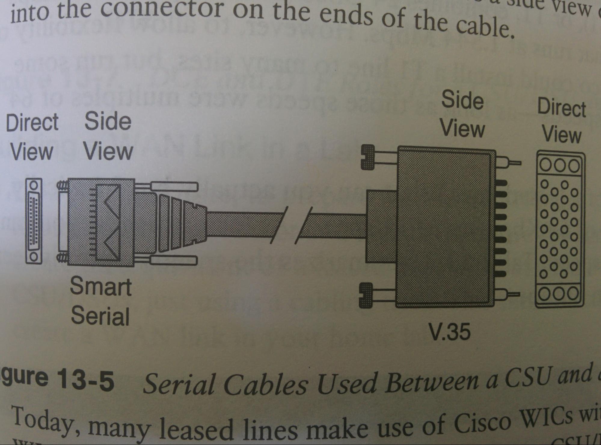
Today many leased lines have an integrated CSU/DSU. I.E. the WIC interface card has a CSU built into the add-in card, so an external one is not needed.
R(config)# int s0/0/0
ip address [x.x.x.x] [x.x.x.x]
encapsulation [hdlc] ! OPTIONAL: default is hdlc, and therefore this cmd is usually optional. could be ppp or maybe others.
bandwidth [kbps] ! OPTIONAL: use this to document the speed so that it matches the actual clock rate of the link. This does not change the actual speed!
show controllers serial [number] ! Lists DCE or DTE end, cable used, & clock rate
clock rate [bits/s] ! NOTE: Only do this on the DCE (CSU/DSU) end ! (e.g. SP or lab environment, not a Cx environment) (speed is in bits per second)
show interfaces s0/0/0 ! BW configured, encapsulation being used (e.g. HDLC/PPP)
- WAN Speeds:
- There is the T-carrier System, which may only be applicable to serial WANs. It is as follows:
|
Names of Line |
Bit Rate |
|
DS0 |
64 Kb/s |
|
Fractional T1 |
Multiples 64 Kb/s (up to 24X) |
|
DS1 (T1) |
1.544 Mb/s (24 DS0s, for 1.536 Mb/s + 8 Kb/s overhead) |
|
E1 (Europe) |
2.048 Mb/s (32 DS0s) |
|
Fractional T3 |
Multiples of 1.536 Mb/s (up to 28X) |
|
DS3 (T3) |
44.736 (28 DS1s, plus mgmt overhead) |
|
E3 (Europe) |
Approx. 34 Mb/s (16 E1s, plus mgmt overhead) |
- CSU:
- Sits between the CPE R and the SP’s leased line. It understands the L1 conventions of both worlds, and can translate between the 2. On the telco end, it can understand the T-Carrier system, TDM, and the speed used by the SP. On the Cx end,
- Cabling:
- You can setup a mini version by connecting two routers serial ints via one of two methods. One options is to use a DTE cable to a DCE cable, with the DTE cable acting as a straight-through cable and the DCE cable acting as a crossover cable. You could also acquire a single cable that does the same job of those two cables combined, search the web for “Cisco serial crossover”. Finally in the example below, R2 needs to use the “clock rate” cmd on the serial interface to assign the clock rate. This will only work correctly if the device the cmd is entered on has a DCE cable connected to it. Newer IOS versions will automatically set the clock rate when DCE cable is detected, but older versions will require that the cmd be entered manually.
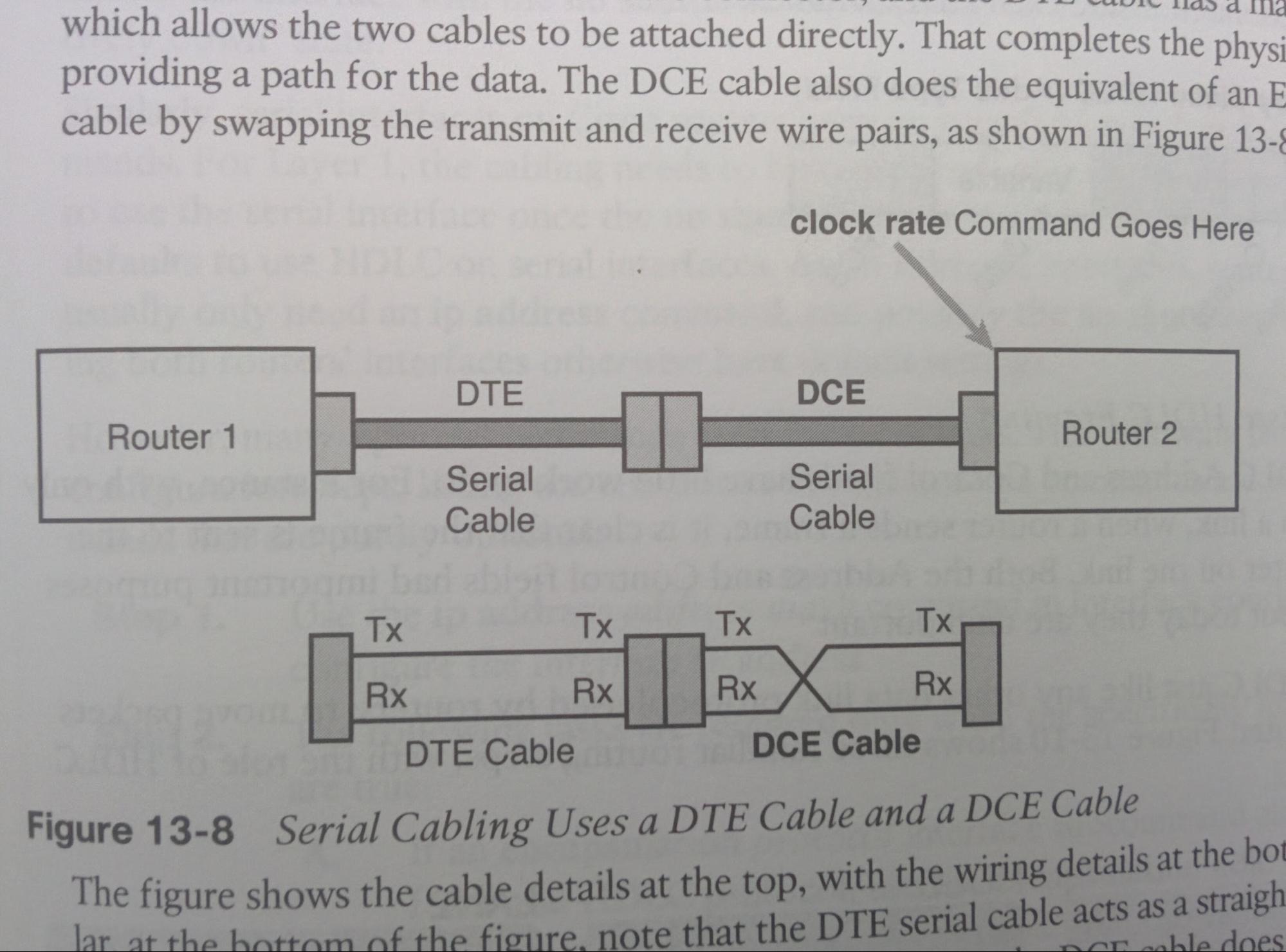
PPP: Point-to-Point Protocol
- PPP:
- Point-to-Point Protocol
- PAP:
- Password Authentication Protocol
- CHAP:
- Challenge Handshake Authentication Protocol
- LCP:
- Link Control Protocol
- NCP:
- Network Control Protocols (e.g. IPCP, IPv6CP, CDPCP)
- IPCP:
- Internet Protocol (v4) Control Protocol (an example of a PPP-NCP)
- IPv6CP:
- Internet Protocol version 6 Control Protocol (an example of a PPP-NCP)
- CDPCP:
- Cisco Discovery Protocol Control Protocol (an example of a PPP-NCP)
- MLPPP:
- MultiLink Point-to-Point Protocol
- LQM:
- Link-Quality Monitoring (feature of PPP-LCP)
- HN:
- Hostname
- PW:
- PassWord
- PPP:
- Provides same role as HDLC, which is a L2 protocol on serial links. While HDLC was intended without Rs, PPP was. Important features in a leased line environment: supports synchronous and a synchronous links, has a protocol “type” field in the header (HDLC does not, but Cisco-HDLC does) allowing different L3 protocols to be used. built-in authentication tools (including PAP and CHAP), and finally “Control protocols for each higher-layer protocols that rides over PPP, allowing easier integration and support of those protocols”.
- PPP Framing:
- The PPP frame is the same as the Cisco-HDLC frame. WIth the following 6 parts: [Flag, Address, Control, Type, Data, FCS] . Using the following number of bytes [1.1.1.2.X.2] (X=variable # of bytes)
- PPP Control Protocols:
- Like how ethernet has STP as a control/overhead protocol to help make ethernet better, PPP also has control protocols. PPP separates the protocols into LCP (Link Control Protocol) & NCP (Network Control Protocols). PPP uses 1 instance of LCP per link, & 1 instance of NCP per protocol on that link. e.g. 1 link that uses IPv4, IPv6, and CDP would use 1 instance of LCP, & 3 instances of an NCP (those being IPCP, IPv6CP, and CDPCP).
- PPP LCP:
- Link Control Protocol is a single protocol w/ different functions, each focused on L2, ignoring L3. LCP is used to automatically agree upon the encapsulation format options, handle varying limits on sizes of packets, detect a looped-back link and other common misconfiguration errors, and terminate the link
|
Function |
LCP Feature |
Description |
|
Looped link detection |
Magic number |
Detects if the link is looped, and disables the int, allowing rerouting over a working route |
|
Error detection |
Link-quality monitoring (LQM) |
Disables an int that exceeds an error percentage threshold, allowing rerouting over better routes |
|
Multilink support |
MLPPP |
Load balances traffic over multiple parallel links |
|
Authentication |
CHAP (or alternatively PAP) |
Exchanges names and passwords so that each dev can verify the ID of the other. |
- PPP NCP: Network Control Protocols are a groups of protocols, one specific per L3 protocol. (e.g. IPCP, IPv6CP, CDPCP)
- PPP Authentication: Most often needed on dial lines, but can still be used on leased lines. Can use CHAP or alternatively PAP.
! config is same near identical to HDLC
R(config)# int s0/0/0
ip address [x.x.x.x] [x.x.x.x] ! OPTIONAL: with PPP, this is actually optional.
encapsulation [ppp] ! default is hdlc, and therefore this cmd is required
bandwidth [kbps] ! OPTIONAL: use this to document the speed so that it matches the actual clock rate of the link. This does not change the actual speed!
show controllers serial 0/0/0 ! Lists DCE or DTE end, cable used, & clock rate
clock rate [bits/s] ! NOTE: Only do this on the DCE (CSU/DSU) end ! (e.g. SP or lab environment, not a Cx environment) (speed is in bits per second)
show interfaces serial 0/0/0 ! BW configured, encapsulation being used (e.g. HDLC/PPP). Should see “Encap PPP, LCP Open” meaning LCP has successfully completed.
PPP w/ PAP
Point-to-Point Protocol with Password Authentication Protocol
Initiator needs to be authenticated, and is performed by the initiator sending the pre-shared plain-text password and their hostname. If the one being authenticated has sent the correct pre-shared plain-text password, the authenticator sends an ACK.
R1(config)#
int s0/0/0
encap ppp
ppp auth pap
ppp pap sent-username R2 password Pa$$ ! other R must do “username R2 password Pa$$
do show interfaces serial 0/0/0
do show ppp all
PPP w/ CHAP
Point-to-Point Protocol with Challenge Handshake Authentication Protocol
R1 sends R2 a random number in a challenge, R2 uses MD5 to hash that random number & the suspected password, & sends that MD5 hash to R1. R1 hashes the same random number & the correct locally (or stored on AAA server) stored pre-shared plain-text password via MD5 & compares that with what it received from R2. Next time R1 uses a different number.
R1(config)# hostname R1 ! Hostname is required because CHAP authentication uses hostname as the username.
R1(config)# username [peer’s HN] password [peer’s PW] ! Defines an accepted UN/PW pair on this R. Both the username and password are case-sensitive. In this example, the “peer’s hostname” should be R2.
R1(config)# int s0/0/0
R1(config-if)# ip add [10.0.0.1] [255.0.0.0] ! In (non MLPPP) PPP environments the IP add is optional.
R1(config-if)# encap ppp
R1(config-if)# ppp authentication chap
R2(config)#
hostname R2 ! Hostname is required because CHAP authentication uses hostname as the username.
username [peer’s HN] password [peer’s PW] ! Defines an accepted UN/PW pair on this R. Both the username and password are case-sensitive. In this example, the “peer’s hostname” should be R1.
int s0/0/0
ip add [x] ! In (non MLPPP) PPP environments the IP add is optional.
encap ppp
ppp auth chap
#debug PPP auth
#debug PPP negotiation
- Verification: “show ppp all” which will show all ppp ints and if their protocols succeeded or failed (by if they have a “+” symbol or a “-” appended, respectively).
“show interfaces serial 0/0/0” || “show interfaces status” to see if L2 line-protocol is up, if it is not, CHAP auth may have failed.
R(config-int)# ppp auth chap pap ! this tries chap first, but will failover to pap. can also reverse this
MLPPP: Multi-Link PPP
WITHOUT MLPPP:
R1 has 2 ints connected to R2, bother serial connections using PPP and each has its own IP. With EIGRp R2 would form two neighbor relationships with R2, and twice the routes. by default IOS would by destination basis, eg all packets to 10.0.2.2 go over the first link, and all packets for 10.0.2.3 over the bottom link. could also change to a packet by packet basis.
WITH MLPPP:
Acts like just one connection. one neighbor, one route, etc. creates a virtual int called a 'multilink int’. the L3 cmds (IPv4 & IPv6) are applied to the multilink int. this virtual int withh fragment packets going to it, into smaller fragments and send those across both physical ppp wires. eg break a packet in half, then re-encapsulate it into Ip packet and a PpP frame (to each half) and send one across each connection. (with a few extra header bytes to account for the fragmentation process). as you would expect if there were 3 links it would be broken into thirds.
to do, configure matchings multilink ints on both Rs, with int subcommands(ipv4 ipv6 routing protocol etc) on the multilink int, not the physical serial ints. configure the physical serial ints w/ all L1&2 cmds like “clock rate …” and “ppp auth …”. configure some ppp cmds on both the virtual ppp multilink int and on the physical serial ints (to associate them)
See also the regular serial interface config so to also put the “bandwidth” and “clock-rate” commands on the correct ints.
|
R1(config)# int multilink 7 ! creates this virtual int. NOTE the number, in this case #7, MUST BE USED ON ALL PHYSICAL SERIAL INTS AND ON THE CONNECTED ROUTER AND ITS VIRTUAL AND PHYSICAL INTS. R1(config-if)# encap ppp R1(config-if)# ppp multilink R1(config-if)# ip add x.x.x.x z.z.z.z ! where x.x.x.x is the ip address, and z.z.z.z is the subnet mask. R1(config-if)# ppp multilink group 7 ! Optional: Add ppp authentication config here (e.g. ppp auth chap), but not on the serial ints.
R1(config)# int s0/0/0 ! and every other serial int for this multilink R1(config-if)# encap ppp R1(config-if)# ppp multilink R1(config-if)# no ip add R1(config-if)# ppp multilink group 7
! once again that 7 must be the number used on the R1’s virt ppp multilink, ALL of R1’s physical serial ints, R2’s virt ppp multilink, and ALL of R2’s phy serial ints.
! VERIFICATION
! verify, should see Mu7 or Multilink 7 instead of s0/0/0. show ip route, show ip int brief (sho ip int brief will list Mu7 w/ an IP but the serial ints without one, this is good). show ip int brief, if up/up means this IOS believes that at least one of the phy serial ints in the virt multilink is working, i.e. if 3 phy ints exist in multilink and 2 are down and 1 is up, show ip int brief will still list the multilink as up/up.
# show interfaces multilink 7 ! notice 1st line, multilink7 is up, line protocol is up. …. multilink open (on right side).
! which phy serial ints working? # show ppp multilink ! notice memberlinks: 3 active, 0 inactive. and it will list which ones.
Ping from one serial int to the other. Success=Check Routing Protocol. Failure=Show ip int brief (on both devs) and fallow table below. |
Ping from one serial int to the other. Success=Check Routing Protocol. Failure=Show ip int brief (on both devs) and fallow table below.
|
Serial Link Troubleshooting |
|
|||
|
Lines Status |
Protocol Status |
Likely Issued Layer |
Possible reasons |
cmd to verify/fix |
|
Down |
Down |
L1 |
int shutdown or hw issue¹ |
no shut |
|
Up |
Down (1 end) |
L2 |
UP end’s keepalive disabled2 (HDLC) |
no no keepalive |
|
Up |
Down (both) |
L2 |
PAP/CHAP auth failure |
“debug ppp auth”, shut no shut int |
|
Up |
Down (1+flip3) |
L2 |
Mismatched encap cmds |
show running-config |
|
Up |
Up |
L3 |
IP or Routing protocols |
same subnet?4 |
- hw issue¹:
- Hardware. For example, Either dev is “administratively shutdown” with the “shutdown” cmd, bad cable between R/ serial int and CSU, misconfigured/broken CSU, SP facilities issue. If ping fails, possible L1 issues:
- “Keepalive” disabled2:
- Keepalive msgs are routinely sent between devices to tell the other to “keepalive” them. Essentially Hello msgs that say “I’m still alive”. If one devices stops sending, the other assumes it is no longer alive and will move that int to UP/down. Keepalive is enabled by default, and this issue only happens with L2-HDLC. Check for a “no keepalive” interface subcmd on the int that stays UP/UP. “Show interfaces” to see keepalive settings.
- 1+flip3:
- 1 end down, other flipping between up/up & up/down.
- 4:
- If in same subnet, HDLC pings will fail, but PPP pings will succeed (because PPP creates a ‘host route’, aka a /32 route). In both, routing protocols will fail.
Dialer Interface
Dialer ints have been in IOS for a long time. Originally used when a R used dial-up tech to make a phone call to another dev to setup a physical link. Today they are used as logical ints that bind to another int to cooperate to perform a certain task. For example, pppoe.
PPPoE: Point-to-Point Protocol over Ethernet
PPP normally on serial ints (including those links created w/ dial-up analog and ISDN modems). But PPP can be transported over ethernet frames with the same benefits, such as different control protocols, & ppp authentication. ISPs use PPP because: can assign an IP to a customer, support CHAP (which ISPs often want to use). PPP was hot stuff in the 90s and early 2000s with the analog modems, until DSL (via the phone line) and its faster speeds started becoming the norm, so a new RFC was created for PPPoE. PPPoE was needed because Cx computer ethernet NICs and Cx router ethernet ints did not understand PPP, only ethernet frames, so PPPoE is a way to tunnel PPP inside of L2 Ethernet frames. PPPoE creates a PPPoE session rather than a PPP point-to-point physical link. ([L3 IP packet] within [L2 PPP frame] within [L2 PPPoE frame] within [L2 Ethernet frame]. Each with a header)
Configuration:
NOTE: PPPoE is more difficult to setup than other things (so the book says at this point). You configure PPPoE from a couple different configuration modes, then PPPoE automatically adds some other important config. These PPPoE config concepts work on both a crossover ethernet link or a DSL link (from the customer’s end). The logical/virtual dialer interface will use the physical g0/0 interface in the example. The dialer interface will have all of the L3 configuration but just use int g0/0 as a media to communicate.
|
! Client / Customer Router Config: Cx-R(config)# int dialer 2 ! The dialer interface holds the PPP information used to create the PPPoE session. ! L3 details below Cx-R(config-if)# ip address negotiated ! PPP uses IPCP (IPv4 control protocol) Cx-R(config-if)# mtu 1492 ! Default=1500 , but PPPoE header adds 8 bytes, so we reduce it to prevent IOS from doing unneeded work to fragment packets. ! L2 details below Cx-R(config-if)# encap ppp Cx-R(config-if)# ppp chap hostname USER1 Cx-R(config-if)# ppp chap password PASS1 ! L1 details below Cx-R(config-if)# dialer pool 1 ! This cmd attaches this int to dial-pool 1, which is attached to int g0/0 below, therefore this attaches dialer 2 to g0/0. This is a pool of ethernet ints that PPPoE can use. Cx-R(config)# int g0/0 ! Physical interface - the one connected towards the ISP Cx-R(config-if)# no ip address ! physical link has no L3 address (L3 command) Cx-R(config-if)# pppoe-client dial-pool-number 1 ! puts this int in dial-pool 1, and that it is available to be used by dialer ints wanting to do pppoe. (L1 command) Cx-R(config-if)# pppoe enable ! auto generated by “pppoe-client dial-pool-number 1” (L2 command) Cx-R(config-if)# no shut ! You could also add a default static route with “ip route 0.0.0.0 0.0.0.0 dialer 2”. (sending to dialer 2 will use dialer 2’s config, which will forward via g0/0.)
! ISP Router Config: ISP-R(config)# ip local pool WOPool 10.1.3.2 10.1.3.254 ISP-R(config)# bba-group pppoe WOGroup ISP-R(config-???)# Virtual-template 1 ISP-R(config)# Username USERA password PASS1 ISP-R(config)# int virtual-template 1 ISP-R(config-if)# ip add 10.1.3.1 255.255.255.0 ISP-R(config-if)# peer default ip address pool WOPool ISP-R(config-if)# ppp auth chap callin ISP-R(config)# int g0/2 ISP-R(config-if)# no ip add ISP-R(config-if)# pppoe enable group WOGroup ISP-R(config-if)# no shutdown |
! (PPPoE Verification)
Theory: Both the dialer int, and the Ethernet int are enabled and used to setup the PPPoE session, if the configs are relatively correct, the PPPoE session will create a “Virtual-Access” interface. This Virtual-Access interface will bind to both the dialer interface and bind to the Ethernet interface. The Ethernet interface is used to send frames; the Virtual-Access interface is used to send PPPoE frames using the ethernet interface; The Dialer interface (L3) is used to send actual packets using the Virtual-access interface (responsible for adding the PPPoE header) and the Virtual-access interface forwards it to the ethernet interface which actually sends the frame.
show interfaces dialer ! Lists output for two interfaces; one group of ~20 output lines for the dialer int, and another set for the virtual-access int to which it is bound. (both will mention being bound to the other)
Dialer = L3
Virtual-access = L2 (config wise that is. It is bound to the Ethernet int.)
show interfaces dialer [2]
- ! This single cmd will list the details for the dialer int, then followed by the details of the virtual-access int that it is bound to.
- Notice “Line Protocol up (spoofing)” (says spoofing because the L2 logic sits elsewhere, in this case on Vi2)
- Notice the learned IP address
- Notice the MTU of 1492 bytes
- Notice encap PPP
- Notice int bound to Vi2 (the virtual int).
- Notice Dialer int LCP closed because it does not do the ppp/pppoe work/function, but Vi# LCP status open because it does do the ppp/pppoe work/function
- You can also do “show interfaces virtual-access 2” to see just that stuff
Verifying Virtual-Access Interface Config:
show interfaces virtual-access 2 configuration ! or “show int vi2 conf” for short
- NOTE: The config cmds listed here will not show in the running config under “show run interface virtual-access2
- Notice the first line of output: “Virtual-Access2 is a PPP over Ethernet link (sub) interface”. Literally telling you that it is a PPPoE int.
- Notice that it will automatically copy the following cmds from the dialer interface to it: “mtu 1492”, “ppp chap hostname USER1”, “ppp chap password 0 PASS1”. (the ppp chap cmds will not show in the running config)
Verifying PPPoE Session Status:
Concept: When PPPoE starts on Cx R it Tx & Rx PPPoE msgs, (including those for LCP), to decide if PPP session can work. Each R tracks the status of the PPPoE state, shown w/ “show pppoe session”.
show pppoe session
show ip int brief ! should see a route to PPPoE int add via dialer int learned from IPCP.
show IP route ! should see host route (/32) to own PpPoE intvia dialer int and another to device on other end of dialer int(also directly connected, a /32, and via the same dialer int).
PPPoE troubleshooting:
Best to work from L1 upwards.
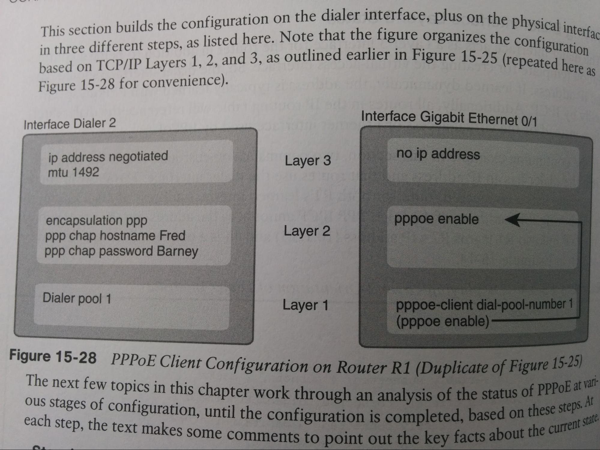
Dialer int: created with”int dialer [2]”
even when misconfigured, or even with no config at all, state
PPPoE w/ CHAP
|
! Cx side int G0/1 no ip add pppoe enable ! auto-generated by “pppoe-client dial-pool-number [7]” pppoe-client dial-pool-number [7] IP TCP Adjust-mms 1452 int DIALER 1 encap PPP ip add negotiated PPP CHAP hostname {ISP side hostname} PPP CHAP password [ISP side password] IP MTU 1492 dialer pool [7] ! ISP side int G0/0 no ip add PPPoE enable group [GLOBAL] IP tcp adjust-mms 1452 bba-group PPPoE [GLOBAL] virtual-template 1 int virtual-template 1 ip add 10.0.0.254 /24 MTU 1492 peer default ip address pool [PPPoEPool] IP local pool [PPPoEPool] 10.0.0.1 10.0.0.10 username [ISP side hostname] password [ISP side password] |
__________
The below information needs to be merged with the rest of the PPP/PPPoE information.
What technology provides service providers the capability to use authentication, accounting, and link management features to customers over Ethernet networks?
PPPoE
What are two characteristics of a PPPoE configuration on a Cisco customer router?
PPP configured on "dialer" int
Ethernet int: no ip add
PPPoE config that must be same on Customer Router:
dialer pool 2
pppoe-client dial-pool-number 2
WANs: Private
Private WANs w/ Ethernet & MPLS
- MPLS: Multiprotocol Label Switching
- EoMPLS: Ethernet over Multiprotocol Label Switching
- MetroE: Metro Ethernet / Carrier Ethernet
- CPE: Customer Premises Equipment
- CE: Customer Edge (usually a router)
- PE: SP Edge (usually a router)
- MPBGP: Multiprotocol Border Gateway Protocol (BGP)
- Route redistribution: Injective routes from one routing protocol into another.
- MPLS and MetroE have been slowly replacing Frame Relay.
Carrier Ethernet / “MetroE”: Metro Ethernet
- MetroE: Metro Ethernet
- Carrier Ethernet: MetroE previously only encompassed a metropolitan area network (MAN) within a city. Today metroE is multi-city, so the term “carrier ethernet” may be more appropriate.
- Access Link: connection (usually fiber) between Cx device to Metro Ethernet SP’s device. Everything on the access link falls into definition of the UNI.
- Ethernet access link: connection (usually fiber) between Cx device to Metro Ethernet SP’s device that uses an Ethernet protocol. Everything on the access link falls into definition of the UNI.
- UNI: User-Network Interface (the interface /access link between user and network. user = Cx. Network = SP)
- EVC: Ethernet Virtual Connection (ethernet connection over a WAN; 1 subnet per EVC; If E-LAN w/ 4 devs, the ‘cloud’ in center is 1 EVC. 1 E-Tree = 1 EVC. 2 E-Lines = 2 EVCS )
- SP: Service Provider
- SP PoP: Service Provider point of presence (where SP’s equipment is)
- What is Metro Ethernet?
- A variety of WAN services, where the SP forwards layer 2 frames (usually using a S) from 1 Cx device to another, usually via 1 of the fiber Ethernet standards due to the distances involved. The Cx will have a device, typically connecting via one of the fiber Ethernet standards due to the distances involved, to a SP PoP L2 device that will forward that L2 frame through to another Cx device. The (typically fiber Ethernet) connection between Cx’s device and the SP’s PoP L2 device is called an “access link”. The CPE devices on each ean of the WAN were historically L3 devs because LAN and WAN ints used to be different protocols & int types, but now they are both ethernet, so it could be a L2 dev now.
- Ethernet Access Links are long-distance, so they may be using different ether standards (some for fiber?) such as:
|
Name |
Speed |
Distance (Km) |
|
100Base-LX10 |
0.1 Gb/s |
10 |
|
1000Base-LX |
1 Gb/s |
5 |
|
1000Base-LX10 |
1 Gb/s |
10 |
|
1000Base-ZX |
1 Gb/s |
100 |
|
10GBase-LR |
10 Gb/s |
10 |
|
10GBase-ER |
10 Gb/s |
40 |
- There are several versions of MetroE/Carrier Ethernet. All are defined by MEF (mef.net).
|
MEF Service Name |
MEF Short Name |
Topology Terms |
Descriptions |
If SP internally uses EoMPLS |
|
Ethernet Line Service |
E-Line |
Point-to-point |
Two CPE devs can exchange frames, like a leased line. |
Virtual Private Wire Service (VPWS) or (generic) EoMPLS |
|
Ethernet LAN Service |
E-LAN |
Full mech |
Like a LAN, all devs can forward frames directly to one another. |
Virtual Private LAN Service (VPLS) or (generic) EoMPLS |
|
Ethernet Tree Service |
E-Tree |
Hub-and-spoke; point-to-multipoint; partial mesh; |
Central hub / root can communicate to all leaves, but leaves can only talk to root/hub. non-hub = leaves |
(generic) EoMPLS |
- If ≥2 E-Line services over 1 access-link, CPE device uses subints & 802.1Q trunking w/ different VLAN ID for each E-Line service.
- 1 subnet per EVC. (e.g. 2 E-Lines = 2 subnets; 1 E-Tree = 1 subnet; see below example for why this is important)
Scenario: 3 Rs, each has only 1 int. R1 connected to R2 via MetroE. R2 connected to R3 over MetroE.
Can R3 and R1 directly talk?
How many subnets are there?
Answers depend on if E-Lines or E-LAN; E-LAN has virtual switch in ‘the cloud’, which E-Lines are virtually P2P / direct.
If E-Lines then R3 & R1 cannot talk directly to one another, must go via R2. There would be 2 subnets, one for each E-Line. (E-Tree = 1 subnet; 2 E-Lines = 2 subnets)
If E-LAN then R3 & R1 can talk directly (through WAN) to one another. There would be 1 subnet.
WAN QoS
- See QoS: WAN
- CIR = Committed information rate (bandwidth that WAN SP guarantees)
- CIR is met via two QoS means. Shaping and Policing.
- Shaping = Customer reduces bandwidth of link to match CIR.
- Policing = SP drops datagrams if customer is sending more than CIR.
MPLS: Multi Protocol Label Switching VPNs
- CE:
- Customer Edge (usually a router)
- PE:
- SP Edge (usually a router)
- MPBGP:
- Multiprotocol Border Gateway Protocol (BGP)
- Route redistribution:
- Injective routes from one routing protocol into another.
MPLS can be used for other things besides MPLS VPNs, but the book only talks about them in this context.
- Define:
- An MPLS VPN is a WAN service that provides a virtually private WAN between Cx edges.
- Private:
- MPLS VPNs are not encrypted, but effectively semi-private. The SP uses MPBGP to make sure packets from one Cx never reach another (even though they may go through the same SP L3 equipment). Logically separated.
- Layer:
- MPLS VPNs provide a L3 service to WAN clients, while MPLS itself is L2.5 since the MPLS header is placed in between the L2 header and the L3 IP header. (in comparison MetroE/’Carrier Ethernet’ provides a L2 service)
- Header:
- PE device (typically router because routing protocols) will add MPLS header between L2 header and L3 IP header when packet received from access-link w/ CE, then removes it when going back over other access-link to dest CE.
- Neighbors:
- PE will form neighbor relationship with CE across access-link via CE’s chosen routing protocol (OSPF, EIGRP, eBGP, etc). So that PE can redistribute Cx routes and networks though SP cloud, to SP devs and to other CEs.
- Routes:
- SP needs to know all subnets of client to know how to route between them (i.e. which CE to send to). Also so It can forwards those routes/network (via routing protocols) to other CE devs so they can talk to one another. Because MPLS is a L3 service, an MPLS SP may receive an incoming packet for a Cx IP that is not a CE IP. This results in the MPLS SP not knowing where to route that packet since that IP could be at different CEs. This is why MPLS SP’s need to use routing protocols and have their PEs exchange and forward routes to and from the CEs, to learn of subnets beyond the CE and tell other CEs about them. The PE devs will redistribute Cx subnets across the WAN to other PE and CE devs. The SP’s MPLS network will use IP routing protocols to determine client’s IP subnets and routes to them.
- Redistribution:
- MPLS SP devs between themselves run MPBGP w/ route redistribution if CE using non-BGP routing protocol. Route redistribution = injecting routes from 1 routing protocol into another (within a single dev). In this case from what the CE is using (if non-BGP) into MPBGP. MPLS SPs use MPBGP because it can adv routes from multiple Cx’s while keeping them logically separate.
- Access links:
- MPLS networks support a variety of access links. Remote sites may not have ‘Carrier Ethernet’/MetroE as an option, but many carriers can install a serial link to remote sites, or the client may replace an existing Frame Relay or ATM network with MPLS, in which case the same physical links can be used and the carrier can transform those over to the MPLS network as MPLS access links.
- QoS:
- With a QoS-Capable WAN, client end can mark packets as high-pri (e.g. VoIP) and WAN / SP can prioritize that by having MPLS. Client’s QoS software places specific value in L3 IP packet header. MPLS WAN SP would then configure its QoS tools to react for packets that have that marking, sending that packet (typically) ASAP.
- OSPF:
- MPLS allows for a couple variations on OSPF area design, but they all use an idea added to OSPF for MPLS VPNs, informally called the “OSPF super-backbone”. Which satisfies the requirement that meets OSPF needs and requirements of MPLS PEs that when they are using OSPF they must be in an OSPF area. MPLS PEs form a backbone area by the name of a super backbone. And each PE-CE link can be any area - a non-backbone area or the backbone area. The OSPF super-backbone (in simple terms, there is actually more) is the majority of the OSPF backbone, but with the option to make the backbone larger (i.e. adding some non SP devices to the backbone as well), It is the client’s choice of what client devices are part of the backbone and which are not. For example, for a nice clean design could be all CE devices Including their access-links) are part of a separate area (e.g. 4 sites are each area 1, 2, 3, and 4 respectively) with the PE devs being in the super backbone (area 0). In the situation where one client is migrating from a different type of WAN with an existing OSPF design, they may prefer to keep some parts of the existing OSPF backbone in that same area.. In fact multiple WAN sites can be configured to be in the backbone area and still function correctly. Area 0 must be contiguous.
- EIGRP:
- The PE-CE configuration at each site (including the CE and Cx networks) could each use a different EIGRP ASN in the configurations, because of the effects of route redistribution to exchange routes. This is because what happens in the SP could, i.e. between the PEs, is independent of EIGRP (because SP cloud uses MPBGP. However EIGRP metrics would be more accurate if all sites used the same EIGRP ASN. “In fact, if the enterprise did use the same EIGRP ASN, the entire MPLS network’s impact on EIGRP metrics would act as if everything between the PEs (SP cloud) did not exist”. It would look like the SP MPLS cloud was just a single hop extra hop.
Private WANs w/ Internet VPN
- TDM:
- Time-division multiplexing. (uses serial links)
- DSL:
- Digital subscriber line. (uses copper wire)
- ISDN:
- Integrated Services Digital Network
- ADSL:
- Asymmetric DSL (upload and download bandwidth are different) Speeds are typically ~5Mb/s, up to ~24Mb/s.
- SDSL:
- Symmetric DSL (upload and download bandwidth are the same)
- WiMax:
- Long distance point-to-point & cellular access
- Telco:
- Telephone Company
- Modem:
- Modulator Demodulator
- DSLAM:
- (DSL) Digital Subscriber Line Access Multiplexer
- CO:
- Central Office (like a PoP. ‘point of presence’)
- CATV:
- Community Access Television or Community Antenna Television. I believe it uses coaxial cables. Used to provide consumers with cable television and subsequently cable internet. (Not the save as CAT5)
- Types of access-links:
- Telephone line, TV cabling, wireless, & more. Businesses often use TDM serial links, MPLS, or MetroE/’Carrier Ethernet” as access-links to ISP to connect to the internet.
- Idea:
- Businesses can use VPN tech, including encryption, to create WAN via public internet, connecting to create an effectively private WAN.
- DSL:
- Uses the copper, same copper as the local link (telephone line). big speed improvement over analog modems of the time (used with ISDN?). Can be used with the same access-link of phone lines. Runs over same phone line to consumer’s location. Because both digital (data) and analog (voice) signals are going over the same access-link at the same time, the telco uses a DSLAM to separate them. Speeds degrade as cable length to CO increases.
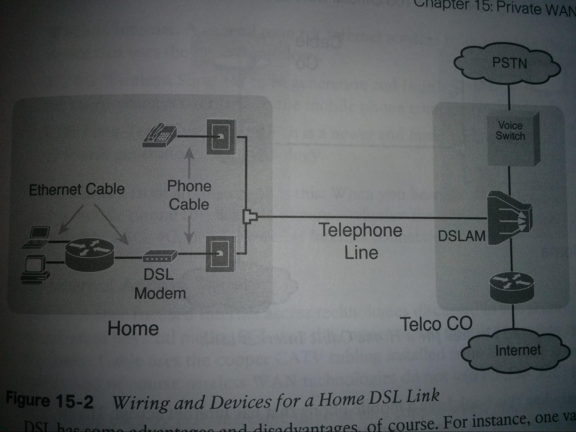
- Cable Internet:
- Cable internet uses the same copper cable that is used to provide consumers with television, which is CATV. Typically providing asymmetric speeds. (not the same copper line as DSL)
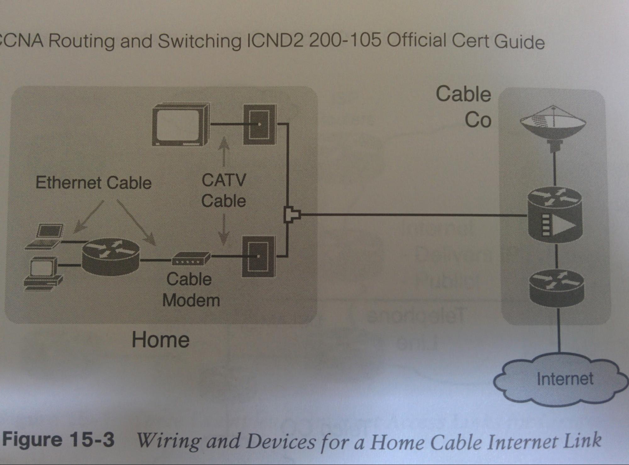
- Wireless WAN (3G, 4G, LTE):
- Mobile devices (such as mobile phones, laptops, and even routers with the correct interface cards) can use their relatively small antenna to send radio waves to communicate with a SP tower’s typically much larger antenna atop a tower within a few miles of the mobile dev. This antenna connects to the SP’s router, of which that connects to the SP’s IP network, which connects to the internet. 3G is short for 3rd generation, and 4G is short for 4th generation. These are just marketing terms and do not specify actual speeds. LTE (short for Long Term Evolution) is like 4.5G.
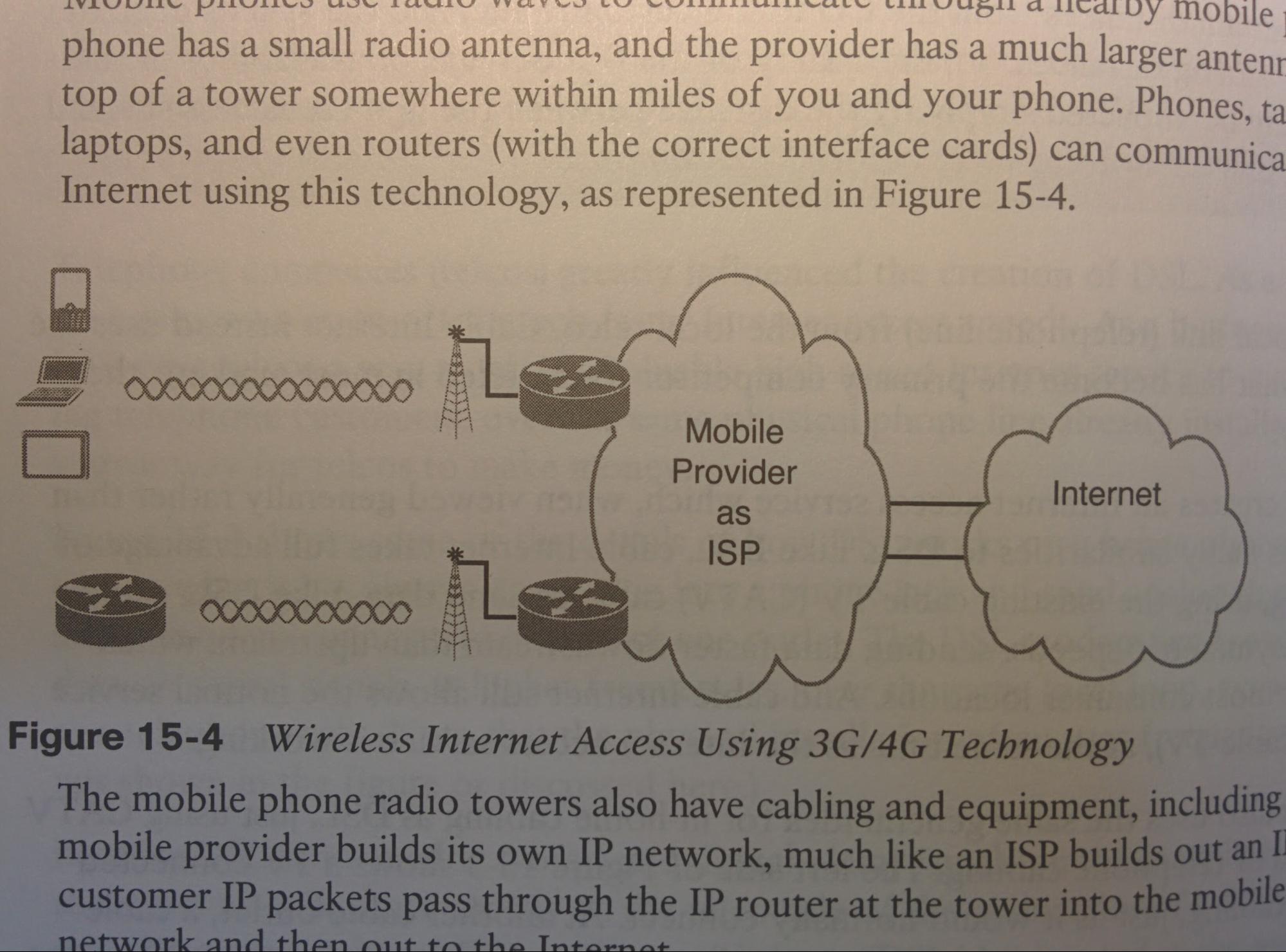
- Fiber Internet:
- Faster than DSL and cable internet, and can support longer distances to the CO. Typically uses ethernet protocols. Fiber SP requires rights to install cabling underground. Typically this is the telcos since they usually already have it to install the copper phone cables (also used for DSL).
Tunnel:
Any protocol’s packet that is being sent by encapsulating that into another packet. May or may not use encryption, although in production is usually is.
IPsec:
IP Security (RFC 4301 Security Architecture for the Internet Protocol). A framework for security service for IP nets, defining how two devices can communicate over the internet securlly.
Encryption Key:
AKA session key, shared key, shared session key.
ASA:
Cisco Adaptive Security Appliance (a line of Cisco firewalls)
- Internet VPNs:
- Can provide authentication (talking to correct entity), data integrity (data has not been altered en route), confidentiality (prevents others from seeing), and anti-replay (prevents data from being replayed at a later time by an imposter). Two devices that are trying to communicate create a VPN tunnel between themselves. Afterwards packets that are destined from one to the other, will be encrypted and have a VPN header slapped on them, followed by another IP header (using public IP adds) being slapped on top of that. Internet VPNs (Cx uses a VPN tech to communicate across an internet connection) typically cost much less than a WAN. Internet connections are available in more areas than WANs.
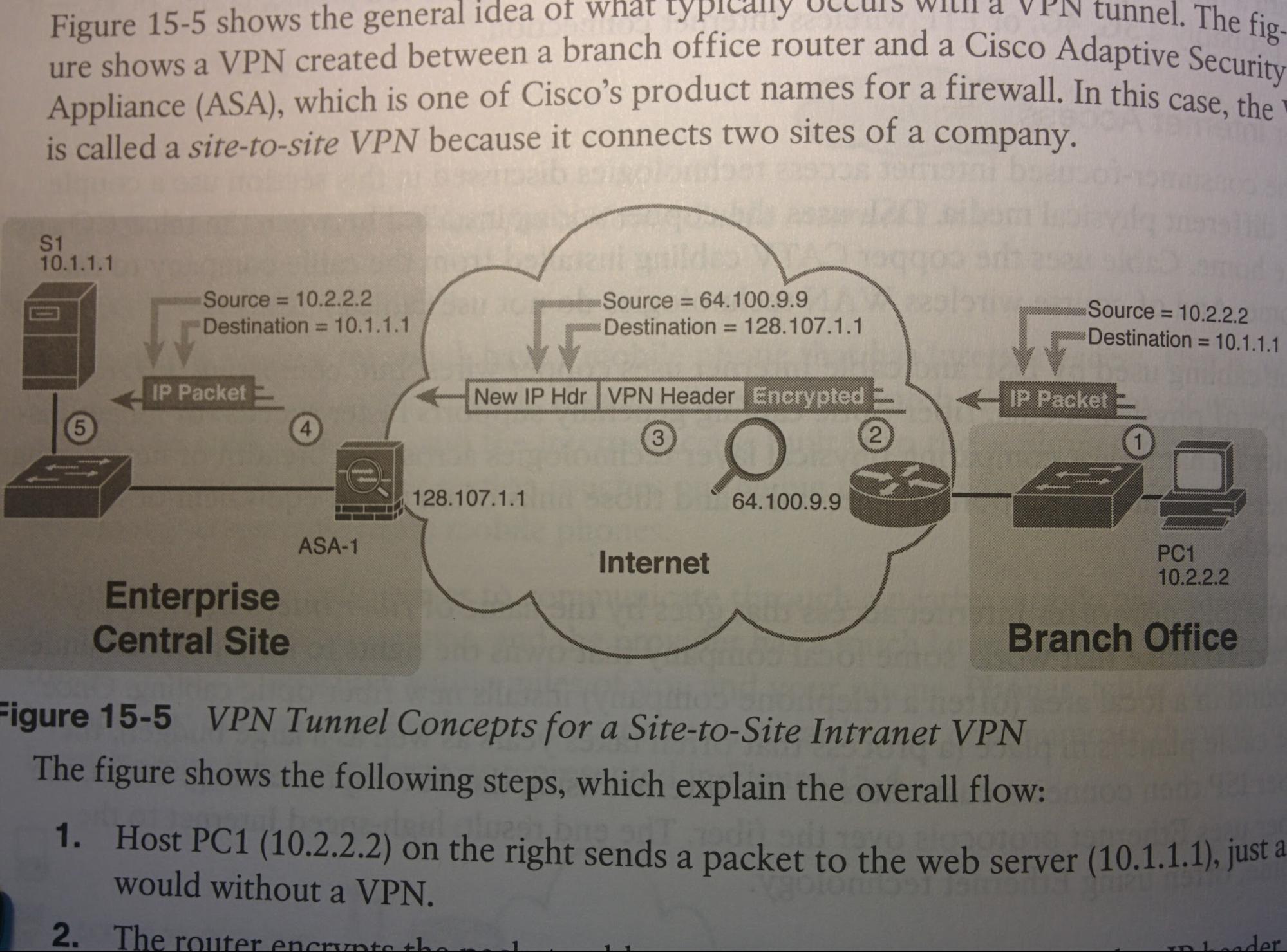
- IPsec:
- IPsec encryptions uses two different math formulas, one to encrypt the data, and one to decrypt the data. Even if an attacker has access to the encrypted data, without the encryption key, they are not able to use the data in any meaningful way (e.g. decrypt it).
- Cisco AnyConnect:
- Cisco AnyConnect Secure Mobility Client is software that runs on a computer, that creates an SSL remote-access tunnel (same SSL used in HTTPS / secure web browsing).
- GRE Tunnels:
- Does the encapsulation portion of a VPN but (by itself) without the encryption. See GRE section of this document.
Multipoint Internet VPNs using DMVPN
- NHRP:
Next Hop Resolution Protocol
- How Similar:
- Still uses GRE and IPsec.
- How New:
- With a multipoint tunnel, any site (hubs & spokes) can communicate with any other site on the same multipoint tunnel. No additional configuration needed on hub for new spokes. Only 1 tunnel int is needed on hub.
- Hub Config:
- Hub no longer needs to manually enter “tunnel destination [ip]” cmds, it will auto request that from new spokes via NHRP msgs.
- NHRP:
- The hub/root site acts also a an NHRP server, which stores a new table with the mappings of public to private IP addresses of all spokes, and can distribute that to spokes so they can create tunnels between themselves.
- New Spokes:
- New spokes (not hub) will need to be configured to connect to hub (i.e. “tunnel dest” cmds) via multipoint tunnel (hub also using multipoint). Then the hub/NHRP server will receive the public & private IP addresses of the new spoke via NHRP msgs, and use that to self configure itself (without human interaction) a new route to this new spoke via the single pre existing multipoint tunnel interface.
- Site-to-Site:
- The hub/NHRP server can tell spokes the public/private NHRP mappings over other spokes, so that they can create routes directly to them over the public internet (not via the hub).
HA: High Availability
- HA:
- “High Availability”
- https://www.cisco.com/c/en/us/td/docs/solutions/Enterprise/Campus/HA_campus_DG/hacampusdg.html
- Divided into two categories:
- Focused on networking devices
- Focused on first-hop gateway redundancy
- SV/Supervisor:
- Where the CPU, volatile memory (RAM), and nonvolatile memory (flash) reside. The brains of the device, responsible for all packet forwarding and switching functions. All software processes of a modular switch run on a SV.
- Backplane:
- What physically connects the SVs (supervisors; see below) between themselves and to the ports / line cards. (for VSS it is the physical backplane, for stackwise it is those special cables)
- Line Cards:
- in a chassis (e.g. Cisco 6500), Line cards are the add-in cards with the ints/lines to the other devs, this card connects to the chassis backplane. (think like 48 ethernet ports)
- Effect: With either tech, all planes are joined between the switches.
- Data Plane: eg user data
- Control Plane: eg CDP, VTP, DTP, STP, etc
- Mgmt Plane: eg SSH, SNMP
- Comparison between Switch Stacking & Chassis Aggregation/VSS vs 1 large modular switch:
|
Modular |
Switch Stacking |
|
|
Initially More expensive |
Initially Less expensive |
Initial cost (if stacking 2 switches) |
|
Less expensive |
More expensive (e.g. multiple non-redundant supervisors) |
If stacking ~4+ switches |
Switch Stacking
- Definition:
- Switch Stacking is used to combine multiple access-layer switches that are within the same series, ‘stacked’ directly above or below one another in the same physical rack and connected via special types of ‘stacking cables’ and special ‘stacking ports’, to create one logical switch.
- Benefits:
- Only 1 (logical) switch must be managed. (synchs ARP, MAC, IGMP, VLAN, and if applicable routing tables)
- This 1 local switch has many ports.
- Minimal latency between the switches (compared to other interfaces between them such as CAT cables).
- Types of Switch Stacking:
-
FlexStack (and FlexStack-Plus)
- Definition:
- A StackWise-based switch-stacking feature tailored for (typically access layer) L2S’s.
- Availability: Typically available on the following Catalyst series switches
- 2960 (some 2960PD, some 2960G)
- 2960-S (some 2960, some 2960G)
- 2960-X
- Requires the “C2960-Stack” module if it is not already built into the S.
- CAB-STK-E-0.5M=
- CAB-STK-E-1M=
- CAB-STK-E-3M=
-
StackWise (and StackWise-Plus)
- Definition:
- A form of switch-stacking.
- Availability: Typically available on the following Catalyst series switches:
- 3560 (some 3560G)
- 3750 (some 3750G and 2948G)
- 3750-E (some 2960-PD, some 2960-G)
- 3750-X
- 3850
- Cables: These cables create a bidirectional closed-loop/ring where each S can two connections to other S’s. This creates the ‘switch fabric’. If there is a disconnection (breakage or whatever) in a part of a cable, the switches in the stack immediately begin to forward in the direction (cable direction) that is still operational.
- CAB-STACK-50CM=
- CAB-STACK-1M=
- CAB-STACK-3M=
- The single config file is shared on all S’s. A brand-new S (without even being powered on previously) can be added to the stack and the current ‘stack master’ will setup the new S with the IOS image, and config file. I.e. a new S can be added without any pre-work on the new switch.
- Master Selection (in order of priority):
- User Selection (via configuration of the “Hardware Priority value”)
- Most Advanced OS
- A switch already programmed (compared to a default switch without configuration)
- Uptime
- Lowest MAC add.
- Naming:
- “StackWise-480” means 480-Gbps stacking.
- StackWise-Plus:
- Supports ‘Local Switching’:
- Locally destined packets need not traverse the stack-ring (the other S’s in the stack).
- Supports ‘Spatial Reuse’:
- Ability to more efficiently utilize stack interconnect (further improving throughput performance)
|
! StackWise VERIFICATION:
S1# show switch
|
||||||
|
|
Switch/Stack Mac Address: ABCD.EF12.3456 |
|||||
|
Switch# |
Role |
Mac Address |
Priority H/W |
Version |
Current State |
|
|
*1 |
Master |
ABCD.EF12.3456 |
1 |
0 |
Ready |
|
|
2 |
Member |
ABCD.EF12.3457 |
1 |
0 |
Ready |
|
|
S1# show switch stack-ports
|
||||||
|
|
Switch# |
|
Port 1 |
Port 2 |
||
|
----------------- |
---------- |
---------- |
||||
|
1 |
|
Ok |
|
Ok |
|
|
|
2 |
Ok |
Ok |
||||
|
S1# show platform stack manager all ! in-depth view into StackWise |
||||||
- “Version”: Hardware version number is associated with the S model. Different models can have the same hardware version number if they support the same system-level features.
- ‘Switch Stacking’ uses the “Stacking Ports” of the switches, to connect to one another.
- Each switch connects to two other switches in the stack making a ‘loop’ or ‘ring’ of stacking-ports connecting all switches. (unless only 2 S, then maybe just 1 wire between them)
- A stacking module must be inserted into each S, then connected with a ‘stacking cable’. (stacking cable is full duplex)
- One can add and remove switches from the stack without interruption the rest of the stack.
- “Stack Master”:
- The switch that controls the rest of the S’s. Stack Master does the matching of the MAC add table to choose where to forward frames.
|
FlexStack |
FlexStack-Plus |
StackWise(+) |
|
|
2010 |
2013 |
? |
Introduced |
|
2960-S, 2960-X |
2960-X, 2960-XR |
? |
Switch Model series |
|
10 Gbps |
20 Gbps |
32/64 Gbps |
Full Duplex Speed of single stack link |
|
4 |
8 |
9 |
Max S in one stack |
|
|
|
|
Stack QoS applied... |
Chassis Aggregation / VSS: Virtual Switching System
- Definition:
- Does not require special hardware (ie stacking module), instead uses Ethernet ints.
- More functional, but more complex
- Aggregates 2 S’s
- Typically used in Core & Distribution layer switches.
- EFSU: “Enhanced Fast Software Upgrade”; allows for the upgrade of the IOS version without downtime. This may be available in VSS configurations.
- Availability:
- Typically available on 4500, 6500, and 6800 series switches.
- Multichassis EtherChannel (MEC):
- Two S in a chassis aggregation configuration. MEC allows creation of EtherChannel link even though physical connections do not all go to the same physical S.
- ie Etherchannel physical links connected to this chassis-aggregated-S is divided, some of the physical connection of the etherchannel go to one physical S in the chassis aggregation configuration, and other physical int of the etherchannel go to the other physical-S in the chassis aggregation configuration.
- (make sure to have each of the individual links in the MEC going to a different physical switch (of the switches in the stack))
- E.g. S1 and S2 are in chassis aggregation configuration together. Using MEC, you can create etherchannel that has one physical int going to S1 and other physical int going to S2.
Active/Active Data Plane eg user data
Active/Standby Control Plane eg CDP, VTP, DTP, STP, etc
Active/Standby? Mgmt Plane: eg SSH, SNMP
(Mgmt Plane: you SSH to the Active S, and config is synced to standby S)
- VSL: “Virtual Switch(ing) Link”
- A portchannel of up to 10 Gigabit Ethernet connections, used to carry control and data planes between two switches.
- VSS: “Virtual Switching System”
- Network System Virtualization Technology that combines S’s into 1 virtual S.
- 2 Catalyst S’s connect via a VSL.
- Operation:
- When the VSS is formed:
- Only 1 management plane exists.
- Only the control plane of 1 switch is active, while the other S’s control plane becomes inactive.
- Data plane of both is active.
- Switch Fabric of both is active.
- Both chassis are kept in sync with the inter-chassis SSO (Stateful SwitchOver) mechanism, along with NSF (NonStop Forwarding) to provide nonstop comms even if the supervisor engine or chassis of one member fails.
- Benefits:
- If used in the distribution layer:
- can be used instead of an FHRP.
- Downstream devices (e.g. ALS) that have multiple upstream links (e.g. ALS1 has a link to DLS1 and a link to DLS) can now use MEC to make them into a portchannel.
- ^ Furthermore, one could make those ALS’ into a switch stack and them use all 4 links (2 links from ALS1 upward, and 2 links from ALS2 upward) into a portchannel! No STP blockage!
|
! VSS VERIFICATION S# show switch virtual S# show switch virtual role S# show switch virtual link S# show switch virtual link port-channel |
Supervisor Redundancy Options
- (the above images show, in darker highlight, how much the standby S will initialize while still in standby. The active S does all)
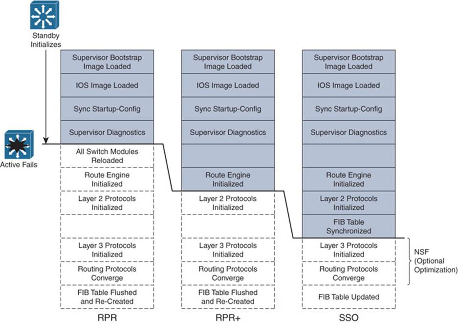
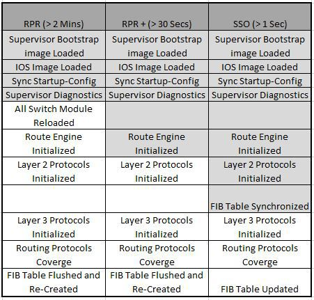
- Used to reduce the impact of a switch failure, particularly in the distribution and core layers.
- SV/Supervisor:
- Where the CPU, volatile memory (RAM), and nonvolatile memory (flash) reside. The brains of the device, responsible for all packet forwarding and switching functions. All software processes of a modular switch run on a SV.
- Redundant Supervisors:
- Multiple SVs allow for redundancy if one of the SVs fail. Reducing a single point of failure.
- First SV to boot becomes the active SV, while the other SVs become standby and wait for the active to fail before 1 will begin operation by taking over, depending on the Redundancy Mode.
- Typically used in distribution and core layers.
- Typically available in the Cisco Catalyst 4500, 6500, & 6800 series switches.
- SV Redundancy Modes: Determines how the SVs handshake, sync info, and the level of the standby SV’s readiness (the more ready, the shorter the failover time).
- RPR: “Router Processor Redundancy”
- Initially, the standby SV is only partially booted, and partially initialized.
- If active fails, standby will: reload every other module, and then initializes all SV functions.
- Failover Time: 2+ minutes.
- RPR+: “Router Processor Redundancy Plus”
- Initially, the standby SV is fully booted, allowing the SV and route engine to initialize (but no L2/3 functions are started just yet).
- If active fails, standby will: finish initializing without reloading the other modules. Allowing the ints to retain the state.
- Failover time: 30+ seconds.
- SSO: “Stateful SwitchOver”
- Initially, the standby SV is fully booted and initialized. The SVs sync startup & running configs, as well as L2 info such as the state of the ints. (to prevent ints from flapping during a failover).
- If active fails, standby will: immediately take over as it has already initialized.
- On 4500 L2 failover is <1 second.
- On 4500 L3 failover (without NSF) requires relearning ARP, CEF, and adjacency tables. During the rebuild of these tables, packets that require routing are dropped (L2 uninterrupted).
- On 6500 L2 failover is 0 - 3 seconds.
- Failover time: 1+ seconds (0 - 3 depending on HW) (this is why it is the most popular).
- SSO also allows for NSF (NonStop Forwarding).
- The standby SV(s) will sync it’s CEF table with that of the active SV.
- Allows for rapid rebuilds of the RIB table (Routing Information Base table) which is used to populate the FIB (Forwarding Information Base) table for CEF, which is then downloaded to any S modules that can perform CEF.
- NSF minimizes the failover time during a SV failure by continuing to forward IP packets using the old CEF entries (that were synced) from the previously active SV automatically in the background, while the supported L3 routing protocols (e.g. BGP, EIGRP, OSPF, IS-IS) reconverge (resulting in zero or near zero packet loss). Once reconverged, old CEF entries are discarded for the new ones.
- Routing protocols allow for an SSO w/ NSF device to send a special NSF message to its routing protocol neighbors. This message reports that the device is performing a SV failover and is utilizing SSO w/ NSF allowing it to continue to forward traffic and therefore requests that the other devices (the neighbors) do not allow the neighbor relationship to flap (drop and come back) during the SV failover. The NSF aware routers are not required to be NSF routers themselves.
- Supported on Cisco Catalyst 4500 and 6500 series switches.
- Typically available on Cisco Catalyst 4500 and 6500 series switches.
|
(config)# redundancy (config-red)# mode {rpr | rpr-plus | sso} ! do this on both SVs. All cmds afterwards should be done on active SV (which will sync those changes to the standby S).
(config)# router {ospf pid | eigrp as#} (config-router)# nsf ! This configures the dev to become nsf aware for the IGP (do this on all {ospf | eigrp} devices).
(config)# router bgp as# (config-router)# bgp graceful-restart ! This configures the dev to become nsf aware for the EGP (do this on all EGP devices).
# show redundancy states |
QoS: Quality of Service
- Bandwidth:
- How many bits can traverse the medium at the same time (capacity. the “width” of the road/pipe/wire).
- Delay: How long it takes.
- One-way delay: Host1 Tx datagram, Host2 Rx it. How long did it take?
- Round-trip delay: Host1 Tx datagram, Host2 Rx it, Host2 Tx datagram, Host1 Rx it. Host long did it take?
- Jitter:
- Fluctuations in the ‘one-way delay’, represented in time (e.g. 300ms).
- Loss:
- Percentage of datagrams dropped. (e.g. “2% loss” = 100 datagrams Tx with 98 data Rx’ed). (e.g. when device’s queue becomes full, all additional datagrams are dropped causing loss).
- QoE:
- “Quality of Experience”. What the users feel. We use QoS to impact QoE.
- Batch Traffic:
- Large amounts of traffic that care about bandwidth rather than delay, jitter, loss. (e.g. data backup or file transfers)
- Flow:
- A one-way data stream. (a VoIP call would have 2 flows)
- QoS Tools:
- Classification & Marking:
- Classifies datagrams based on header contents. “Marks” datagram with different marks depending on how it was classified. Marking typically done ingress at “Trust Boundary” by access-layer switches or Cisco IP Phones. to reduce load on networking devices closer to the core. Markings are accepted as valid by other networking devices within the trust boundary (so they don’t have to reclassify, which is taxing on device resources). Implemented in similar fashion as ACLs, enabled on the interface (as Ingress || Egress), when matched takes a certain action (e.g. place in fast/slow queue).
- Other devices will use much simpler logic then the access-layer switches do, such as “if DSCP=1 then fast queue, elif DSCP=2 slow queue)
- QoS classification can just use ACLs. If datagram matches a permit statement in extended ACL “QoS-Fast” then do this.
- (better to mark within the packet rather than the frames, since frames are de&re-encapsulated at each hop)
- “Trust Boundary”: The border between two devices that marks which QoS markings are trusted and which are not. Usually at access-layer switches or the Cisco IP phone (if applicable).
- 1. Tech savvy users can mark all traffic from their PC as high-priority
- 2. Extending the trust boundary closer to end devices lightens the load on the more inner (closer to core) net devices
- DSCP (IPv4): “Differentiated Services Code Point” field. Within IP header is this 6-bit field used for QoS marking. . IPv6 version is “IPv6 Traffic Class” bytes.
- EP (Expedited Forwarding / decimal value of 46).
- DiffServ ~=~ DFCP. E.g. VoIP payload datagrams (not overhead / control / call signaling, those get “CS3”).
- AF (Assured Forwarding):
- 12 DSCP values. E.g. DSCP marking of “AF41” is the best. “AF-” is always the same, the 1st decimal digits represents which queue it is is, with 4 being to best queue and 1 being the worst queue. The seconds decimal digit represents “drop priority” which is how likely we are to drop that datagram for congestion avoidance purposes. In this example, “AF41”, the decimal “1” represents the best drop priority. I.e. the least likely to be dropped. In comparison to “AF43” which would be the most likely to be dropped (in the 4th/best queue that is) for congestion avoidance purposes. Below you can see the table, with the SDCP text names, and with the corresponding DSCP decimal value beneath each one.
|
X-axis: Drop Priority / Probability (more = worse) |
EF (46) |
||
|
Y-Axis: How desirable the queue (more = better) |
AF41 (34) |
AF42 (36) |
AF43 (38) |
|
AF31 (26) |
AF32 (28) |
AF33 (30) |
|
|
AF21 (18) |
AF22 (20) |
AF23 (22) |
|
|
AF11 (10) |
AF12 (12) |
AF13 (14) |
|
- DiffServ (DSCP) Values (Suggested): EF = “Expedited Forwarding”, Low-delay, low-jitter, & low-loss = DSCP Value 46.
- IPv6 Traffic Class: One byte IPv6 version of DSCP, used for QoS marking.
- NBAR:
- “Cisco Network Based Application Recognition” (current version is NBAR2). Uses more than just well-known ports. Can specify >1000 different applications (e.g. facetime, espn-video, amazon-instant-video.)
- R(config)# class-map MatchingExample
- R(config-cmap)# match protocol attribute category voice-and-video ? ! Shows many voice & video “signatures” that NBAR I can identify.
- ToS:
- “Type of Service” is a 1 Byte field in IPv4 Header. Old “RFC 291” defined it as a 3-bit IP Precedence (IPP) field, followed by 5 unimportant bits. But DiffServ redefined it. New “RFC 2474” defines it as a 6-bit DSCP field and a 2-bit ECN field (RFC 3168). NOTE: This new 6-bit DSCP field is backwards compatible with IPP. The 3 IPP bits, are equivalent to the first 3 bits of the DSCP’s 6 total bits (followed by 3 zeros). E.g. IPP 101 = DSCP 101000. See “Class Selector (CS)” below for their alphabetical names.
- Class Selector (CS):
- Alphabetical names to represent a DSCP/IPP value. It’s simple. The first 3 bits in the ToS field in the IPv4 header = IPP binary value = first 3 bits in DSCP value = that number in decimal prefixed by CS. Where you just take the IPP value in decimal and prefix it with “CS”. See “ToS” above. (E.g. “CS2” is IPP 2 (decimal), and DSCP 16 (in decimal). They all share the same binary value for the first 3 bits. Again, see “ToS”.
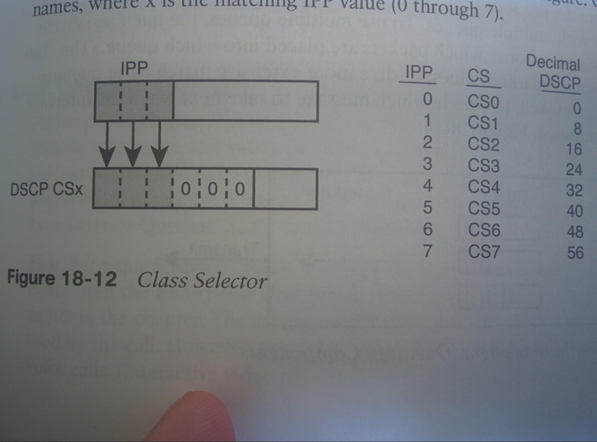
- CoS/PCP:
- “Class of Service”/”Priority Code Point” field. 3-bit field within 802.1Q (trunking) header. Limited to only being used on trunk ports.
- Other places for marking:
- You could also put markins in TID field of 802.11 / over Wi-Fi, or EXP field of MPLS Labels (over MPLS WAN), or DSCP/IPP.
- Congestion Mgmt (Queuing): Managing queues that hold datagrams (waiting for a certain resource, usually an outgoing int to have available bandwidth.)
- A “classifier” puts datagrams into queues, and a Scheduler reads the queues to forward the datagrams (usually using “prioritization”, giving priority to one queue over another).
- FIFO:
- “First In First Out”. Type of queuing system. The sooner a datagram enters this queue, the sooner it will be forwarded.
- Round Robin:
- Type of scheduling where there are multiple queues, and the scheduler (the ‘robin’) goes “around” each queue. Traditionally treating each queue equally.
- Weighted Round Robin:
- Same as “Round Robin”, but the queues are given a “weight”, which the scheduler uses to prioritize queues by how much weight they have.
- CBWFQ:
- “Class-Based Weighted Fair Queueing”. Uses a “Weighted Round Robin” scheduling algorithm but the engineer configures the weights for each queue as a percentage of link bandwidth. It guarantees a (configurable) minimum bandwidth available to each queue. That configurable minimum is the ‘weight’.
- LLQ:
- “Low Latency Queueing”. Creates a queue that receives max prioritization. I.e. device always forwards datagrams from this queue before any other. (possibly causing ‘queue starvation’ of other queues, but this is resolved by policing this LLQ queue with a max bandwidth. But if this LLQ queue uses more than that max that causes dropped datagrams. Solution: reduce LLQ traffic on this int.)
- Queue Starvation:
- A queue never gets serviced by the scheduler. (‘starved’ of bandwidth).
- Shaping & Policing
- Where?:
- Most often used at WAN edge.
- Policing:
- If bandwidth exceeds a certain threshold, drops datagrams (Or marks them differently). Can be configured to, after period of low activity, allow bursts of traffic over the threshold to accommodate “bursty” traffic (e.g. web browsing). Only used in specific situations, such as by a Carrier-Ethernet WAN SP. (Since dropping data grams makes hosts need to retransmit (if TCP)). That SP could also mark those excessive datagrams with a lower priority marking (e.g. DSCP value in packets, CoS/PCP value in 802.1Q, or EXP in MPLS) and add those excessive datagrams to a lower priority queue. In that way, the SP is being nice (extra bandwidth), but can drop/queue those datagrams if the SP network is congested (e.g. if many Cx’s of that SP are sending excessive datagrams).
- Shaping:
- If bandwidth exceeds certain threshold, queues datagrams. (Usually done in conjunction with CBWFQ and LLQ. E.g. done at CE to WAN SP). Enabled on egress traffic on int. Queues excessive traffic, and releases it slowly over time.
- Tc:
- “Time interval”, refers to how the shaper will Tx at max speed of physical int for some time, and then be silent long enough to keep the average transmission rate exactly what is configured to be (e.g. the CIR of the WAN) for that time interval. (e.g. on a 1gbps int, a 200mbps CIR, & a 1s Tc, the shaper will Tx at 1gbps for 0.2s and then be silent for 0.8s ; in this example the ‘time interval’ is 1s.) This can cause unacceptable delays if a VoIP datagram is to be sent, but has to wait that full 800ms (max acceptable VoIP delay is <150ms). Solution is to reduce the Tc. (general rule: use a 10ms Tc if supporting interactive VoIP/Video, in addition to CBWFQ and LLQ).
- Congestion Avoidance
- Tail Drop:
- When a datagram is placed in a queue, it is put at the end of that queue, i.e. the tail. When the queue is full, the tail is dropped.
- TCP Window:
- TCP will continue to increase the window size as long as there are no packets dropped, eventually sending a non-stop stream of data so long as no drops. If a packet is dropped it will half the window size (multiple drops, multiple halfings / multiple reductions).
- Congestion Avoidance Tools:
- Drops some packets to attempt to lower window sizes to reduce traffic, and attempt to avoid congestion in the future. As congestion increases, congestion avoidance will increase the number of datagrams dropped. (when and how much is configurable).
- QoS Requirements:
- Video:
- Bandwidth: Varies. >384kbps to >30mbps
- One-way Delay: 200-400ms
- Jitter: 30-50ms
- Loss: 0.1-1%
- VoIP:
- Bandwidth: Varies by codec. >80kbps (w/ G.711 codec) >24kbps (w/ G.729)
- One-way Delay: <150ms
- Jitter: <30ms
- Loss: <1%
QoS: WAN
CIR = Committed information rate (bandwidth that WAN SP guarantees)
CIR is met via two QoS means. Shaping and Policing.
Shaping = Customer reduces bandwidth of link to match CIR.
Policing = SP drops datagrams if customer is sending more than CIR.
QoS: VoIP
- Trust Boundary: The border between two devices that marks what QoS markings are trusted and which are not.
- Extending/pushing the trust boundary closer to end devices lightens the load on the more inner (closer to core) net devices, which is good.
- Tech savvy users can mark all traffic from their PC as high-priority
- Where to place the trust boundary?
- trust boundary may divide desktop and VoIP-phone as trust boundary (prefered)
- may divide VoIP phone and access-layer-S, as trust boundary
- may divide access-layer-S and distribution-layer devices as trust boundary
|
S(config)# int fa0/1 S(config-if)# auto qos voip trust ! configures AutoQoS default policy, also makes config changes in other parts of config S# sh run int fa0/1 ! notice many changes
R(config)# int g0/0 R(config-if)# auto discovery ! monitors int over extended period of time to create custom AutoQoS policy, which can be applied or ignored. R(config-if)# auto qos voip trust ! implements default AutoQoS policy R# sh run int g0/0 ! notice “auto qos voip”, “ppp …”?, “service-policy output AutoQoS-Policy-trust”, maybe more? |
Wireless
- AP: “Access Point”; typically synonymous with WAP.
- WAP: “Wireless Access Point”’ (typically synonymous with AP, but WAP is more specific to wireless)
- LAP: “Lightweight Wireless Access Point”; WLC/Controller-based WAPs, not standalone. (sometimes called LWAPPs, or LWAPs)
- WLAN: “Wireless LAN”;
- WLC: “WLAN Controller”; Can be Standalone devices (typical WLCs), integrated into a S (from the MFG), or virtualized. (an example of a WLC/WLC software is Cisco Prime)
- 802.11: The standard used for wireless communication, set forth by the IEEE.
- PoE:
- “Power over Ethernet”; IP-phones & WAPs get both power and network access via the same connection, so they do not require an additional cable plugged in for power, making it much more scalable. Both devs on the wire must support PoE for it to work (e.g. both the WAP and the S).
- Frames: 802.11 frame =/= 802.3 (ethernet) frame.
- Int to AP: Trunks are setup to connect to APs from the S.
- Cisco Offers two WLAN implementations/solutions:
- Standalone: Based on autonomous/standalone APs.
- WAPs are configured individually at the WAP itself.
- WAPs act as extensions to the S int.
- WAP converts the 802.11 frame to an 802.3 frame, with the client MAC add used as the SA (i.e. source address).
- Controller-based: Based on controller-based LAPs and WLCs.
- Management, control, deployment, and security functions are moved to a central point: the WLC.
AAA w/ RADIUS & TACACS+
- AAA:
- “Authentication, Authorization, & Accounting”; A framework used to enforce the network access control policy on network devices. Benefits: Logins stored in a centralized, possibly redundant, location compared to local logins, allows control over per-cmd / per-int configuration by users (unavailable with local credentials). AAA is open standard and allows different brand devices and different AAA servers while being interoperable.
- AAA Authentication:
- The process of identifying a user before they are granted access to a protected resource (e.g. the network). User provides credentials requested by the network. Other services may be offered such as encryption or messaging support.
- Generally based on (or combination of) what the entity:
- Knows (e.g. password)
- Has (e.g. digital certificate issued by CA)
- Is (e.g. biometric scanners testing retinas or fingerprint)
- AV Pairs:
- Attribute-value pairs; Associated with an entity (usually a group, alternatively an individual user). Used to define entity’s allowed functions/capabilities (e.g. An AV pair is “shell:priv-lvl=15”).
- AAA Authorization:
- After user is authenticated and granted access to the network, authorization controls what level of access is granted via AP Pairs (e.g. which privileged EXEC cmds are allowed, or control remote access / use of PPP or Serial Line Internet Protocol “SLIP”). This is done when the user attempts to perform a specific function on the device (e.g. the R or S), the device’s AAA engine queries the configured authorization server (a centralized TACACS+/RADIUS server, or alternatively itself) for the AV pair for that specific function that is associated with that entity. The device will know the entity, and the attribute, but requests the value of that attribute.
- AAA Accounting:
- Collection of into about user activity and resource consumption in the form of AV pairs (e.g. user logins, cmds executed, session durations, bytes transferred, etc.). This is Tx’ed to the accounting server (may be for billing, auditing, and/or reporting purposes).
- Service Type: (authentication)
- ?
- Supplicant:
- A piece of software/code that is requesting access (end user’s device on behalf of the user). The supplicant could be 3rd party supplicant software, or the supplicant could be backed into OS.
- AAA Server:
- Cisco provides AAA server functionality via “Cisco Secure Access Control Server (ACS)” and the newer “Identity Services Engine (ISE)”. New versions of Microsoft Windows Server can also act as a RADIUS servers.
- NAS:
- “Network Access Server” (not to be confused with Network Attached Storage). Network device that receives the request from the supplicant (e.g. user) for access, and forwards it to the AAA Server for verification. For example, a switch or router can be a NAS.
|
TACACS+ |
RADIUS |
Features |
|
Networking Devices |
Network Access |
(Typically) Which protected resource is access being requested to with this protocol: |
|
TCP |
UDP |
L4 Transport Protocol: |
|
49 |
1812 & 1813 |
Authentication port numbers: |
|
Yes |
Yes |
Protocol encrypts the password: |
|
Yes |
No |
Protocol encrypts the entire packet: |
|
Yes |
No |
Supports function to authorize each user to a subset of CLI commands: |
|
Cisco (proprietary 1) |
RFC 2865/2866 |
Defined by: |
|
bidirectional |
unidirectional |
Single (1-way) vs multiple (2-way) Challenge response(s): |
|
Cx/Svr |
Cx/Svr |
Model (Client/Server vs P2P): |
1Cisco has published the TACACS+ specification as a draft RFC.
- RADIUS:
- “Remote Authentication Dial-In User Service”
- Before RFC standardization, RADIUS used UDP port 1645 & 1646. Now uses 1812 for authentication, and 1813 for accounting.
- Between the NAS and the RADIUS server, only the password is encrypted.
- RADIUS AAA Communication (UDP):
- User’s request > NAS
- NAS > Access-Request > RADIUS Svr ! Access-Request: Contains Username, Password, NAS.
- NAS < Access-Challenge < RADIUS Svr ! (Optional) Access-Challenge: Reauthentication Parameters (Requesting PIN, token card, etc for Authentication purposes)
- NAS > Access-Request > RADIUS Svr ! (Optional; but required if Access-Challenge sent) Access-Request: Username, password, …
- NAS < Access-{Accept|Reject} < RADIUS Scr ! Contains: “Reply Attribute”-AV pairs (User Service, ..)
- NAS > Accounting Request > RADIUS Svr ! Contains: Accounting Information
- NAS < Accounting Response < RADIUS Svr ! Acks Accounting Info
- The NAS also Txs the pre-shared secret to the RADIUS Svr. This is the pre-shared that authenticates the NAS itself, and proves that the NAS is allowed to even communicate with the RADIUS Svr. This is sent in the first Access-Request sent to the RADIUS Svr. If the RADIUS Svr finds the shared secret a match, it checks the credentials sent in the first Access-Request packet, else it drops the packet (with the reply or ack).
- TACACS+:
- TACACS+ AAA Communication (TCP):
- NAS > START > TACACS+ Svr
- NAS < GET USER < TACACS+ Svr ! (Sends prompt for username)
- NAS > CONTINUE > TACACS+ Svr ! (Sends username)
- NAS < GET PASS < TACACS+ Svr ! (Sends prompt for passphrase)
- NAS > CONTINUE > TACACS+ Svr ! (Sends passphrase)
- NAS < ACCEPT/REJECT < TACACS+ Svr ! (Final Status. If ACCEPT, then it may begin the authorization phase if configured to do so on the NAS.)
- TACACS+ can be configured so, when someone remotely connects to a networking device (eg R or S), the device forwards the login credentials supplied to it, to the AAA server where the server has the information regarding what subset of commands that login is allowed to use(and respond with accept, continue, or error). In contrast to just having user-mode and privileged-mode, TACACS+ can say with greater detail/scrutiny what subset of commands can be entered by that login. In contrast, RADIUS cannot set difference between what subsets of commands each login can do. I.e. while RADIUS combines authentication and authorization into one, TACACS+ can differentiate between the two and provide better security. TACACS+ is not backwards compatible with TACACS or XTACACS (now deprecated). Entire TACACS+ packet is encrypted.
- Authentication Method: (used for Authentication if not more) If multiple methods are defined, attempts the first one, if that errors out/times-out (not if it returns with a deny), tries the next one. Best to use one or more groups and fallback to local. A method (a way/ an option) of querying/verifying AAA information
- group group-name
- A group of remote RADIUS or TACACS+ servers.
- local
- The local DB on the device itself. (think “Dev(config)#username class secret cisco)
- enable
- Uses the enable password.
- line
- Uses the line password.
- LDAP
- The network access server requests authorization information from the RADIUS security server. LDAP authorization defines specific rights for users by associating attributes, which are stored in a database on the LDAP server, with the appropriate user.
- If-Authenticated
- Access is granted if user has authenticated. (this applies to authorization)
- none
- Used as the last method. If used (and all previous methods in the list time-out/error) allows everyone in (very bad). Should use local instead.
- List:
- List Definition:
- Identified with a “list-name”, a list is an ordered ‘list’ of methods (i.e. an ordered procedure of methods), to be used for a certain AAA purpose (e.g. for authentication or authorization). There can exist multiple different lists (i.e. multiple different procedures).
- List Operation:
- The list will list 1 or more ordered methods to be used for AAA purposes. The first method (the leftmost method) will be attempted first. If that method is unavailable (e.g. if the method is “group group-name” and none of the servers in the group respond, that is to say that we ask, but hear nothing back. This is not the same as getting a negative response/ the server responding with “no”. Rather, this is like HOLY SHIT our fucking AAA servers are down!!1) then the next method will be tried. If all methods are unavailable then an error msg is logged and access is denied (similar to how all ACLs have an implicit deny any any at the end). (there is one exception to this with regard to the console port. See “The default list” below).
- The “default” list:
- Out of the box there is only one list, it is the “default” list, its list-name is “default”.
- States:
- The default list has two states: implied and defined. Out of the box the default list does not appear in the running-config but it is there nonetheless, i.e. it is “implied”. If one defines the default list, for example with the global cmd “aaa authentication login default ...”, then it becomes “defined” since it has been manually configured. Defined is always better (see list precedence).
- Implied Methods:
- Although when the default list is defined it can use any methods, when it is implied (i.e. not defined), for all non-console ints/lines, it uses the “local” method only, meaning all authentication (and authorizations?) will run against the local DB. This does not apply to console lines in some specific situations, see the “List precedence” sub-section below.
- Custom/non-default lists:
- One can create other custom/non-default lists, with different list-names. In contrast to the list “default”, these other lists will not take effect unless the line/int is configured to use one of these custom/non-default lists.
- List precedence:
- Only one list may take effect on any given int/line at a time.
- For all ints/lines:
- If the int/line is explicitly configured to use a specific list (custom or default):
- It will use said list.
- Else if the int/line is not explicitly configured to use a list:
- If the default list is defined:
- Then the int/line will implicitly use the defined default list (and its configured methods).
- Else if the default list is not defined:
- If the int/line is not a console line:
- The int/line will use the implied default list (which uses only the “local” method for authentication).
- Else if the int/line is the console line:
- Then the console line will not perform authentication checks (i.e. the console line will allow all connections. It will not use the implied default list).
- Best Practice:
- Backup Login:
- Use TACACS+ or RADIUS as the method(s), but make sure to have the last method be “local” and have a local ‘privilege 15’ user configured before one enters the “aaa new model” cmd. Doing so allows a backup method of accessing the device should comms to the remote AAA server fail (e.g. if the AAA server gets nuked or someone messes up the AAA config on the dev).
- Define the default for con0:
- If console access should be protected but custom lists are not being used, define the default list (even if not using “local” as the primary method). See “the ‘default’ list” for why. The console line uses no authentication checks and all logins succeed. Therefore, it is important to either define the default list (even if simply using only the “local” method), or configure the console line to use either a custom list or another form of authentication for best security.
- Test:
- If configuring AAA, before copying the running-config to the startup-config, and before logging out via “exit”, “end”, or closing the session in any other way, create a new/separate session to the device and verify that one can still log in. This is to say, test the changes with a new session before closing the current working session.
- Authorization-type:
- (these are used in the cmd “(config)# aaa authorization {authorization-type} {list-name} {method1 [method2...]}” )
- A typical example:
- aaa authorization config-commands
- aaa authorization exec default group group-name local
- aaa authorization commands 15 default group group-name local
- aaa authorization reverse-access default group group-name local
- exec:
- This is the main one! Applies to the attributes associated with a user EXEC terminal session. “starting an exec (shell) session”.
- commands:
- Applies to the EXEC mode commands a user issues. Command authorization attempts authorization for all EXEC mode commands, including global configuration commands, associated with a specific privilege level.
- e.g. commands 15 would mean any exec shell cmds at priv lvl 15 (privileged exec).
- config-commands:
- Any configuration mode cmds. all configuration mode commands will fall into this category.
- used in the cmd “config)# aaa authorization config-commands”
- network:
- Reverse Access:
- Applies to reverse (reverse access) Telnet sessions.
- Auth-proxy
- Applies specific security policies on a per-user basis.
- Configuration (same as config-commands?)
- ?
- ipmobile
- ?
- Accounting-type:
- EXEC
- Provides information about user EXEC (shell) terminal sessions of the network access server.
- e.g. The cmd “aaa accounting exec default start-stop group groupName” will apply an accounting requirement for starting an exec (shell) session.
- Commands
- Provides information about the EXEC mode commands that a user issues. Command accounting generates accounting records for all EXEC mode commands, including global configuration commands, associated with a specific privilege level.
- e.g. The cmd “aaa accounting commands 15 default start-stop group groupName” will apply an accounting requirement for any exec (shell) commands at privilege level 15 (privileged exec)..
- Network
- e.g. The cmd “aaa accounting network default start-stop group groupName” will apply an accounting requirement for Network services such as those listed above.
- Connection
- Provides information about all outbound connections made from the network access server, such as Telnet, local-area transport (LAT), TN3270, packet assembler/disassembler (PAD), and rlogin.
- e.g. The cmd “aaa accounting connection default start-stop group groupName” will apply an accounting requirement for outbound connections (e.g. telnet, rlogin) .
- System
- Provides information about system-level events.
- Resource
- Provides "start" and "stop" records for calls that have passed user authentication, and provides "stop" records for calls that fail to authenticate.
- VRRS
- Provides information about Virtual Router Redundancy Service (VRRS).
See: https://www.cisco.com/c/en/us/td/docs/ios/12_2/security/command/reference/fsecur_r/srfathen.html
|
! INITIAL SETUP (config)# username {USER} privilege 15 secret {SECRET} ! Set a local login to be used as a backup in case comms to RADIUS/TACACS+ servers fail. Highly recommended. (config)# ip {tacacs|radius} source-interface {int} ! Declare which int (& subsequent ip add) is used for comms w/ the TACACS/RADIUS svrs. Loopback ints are recommended. (config)# aaa new-model ! Enables many new AAA cmds. Immediately applies local authentication (via the default list) to all lines & ints (except line con0).
! DEFINE THE TACACS+ SERVERS (config)# tacacs server {server-name} ! The new way to define a TACACS+ svr(s). Server-name is only locally significant. (config-tacacs-server)# address ipv4 {x.x.x.x} (config-tacacs-server)# key {key_value} ! This is the pre-shared key used to authenticate this device to, and encrypt comms to the TACACS+ svr. (config-tacacs-server)# port {49} ! Optional. Configures the TCP port to use. Default is 49. ! (config)# tacacs-server host svrIP [key key] ! Old way of configuring tacacs svrs. don’t do this. ! (config)# tacacs-server key key ! Old way of configuring tacacs svrs. don’t do this.
! DEFINE THE RADIUS SERVERS (config)# radius server {server-name} ! The new way to define a RADIUS svr(s). Server-name is only locally significant, & is used to reference this svr in future cmds. (config-radius-server)# address ipv4 {x.x.x.x} [auth-port 1812] [acct-port 1813] ! One may manually specify the ports. In this example the defaults were used. (config-radius-server)# key {key_value} ! Defines the pre-shared secret used to authenticate the NAS. ! (config)# radius-server host svrIP [key key] ! Old way of configuring radius svrs. don’t do this. ! (config)# radius-server key key ! Old way of configuring radius svrs. don’t do this.
! DEFINE A GROUP OF SERVERS INTO A SERVER GROUP TO FORM A METHOD (config)# aaa group server {radius|tacacs+} {method-name} ! Define a AAA Group of (radius or tacacs+) servers to create a method. This group-name/method is what is referenced in future cmds. (config-sg-method)# ip tacacs source-interface int ! This is usually available if global cmd “tacacs source-interface int” is not. (config-sg-method)# server name {server-name} ! List each server-name to be placed into this server group. If this isn’t accepted try “server ip”. (config-sg-method)# server name {server-name} ! In the prompt “config-sg-method”, sg = server group. method will change to your method (radius|tacacs).
! DEFINE AN AUTHENTICATION LIST (a list of ordered methods) (config)# aaa authentication dot1x {list-name} {method1 [method2...]} ! Configures list used for dot1x port-based authentication. Method’s typically ‘group group-name’. See “IEEE 802.1X & EAPOL”. (config)# aaa authentication login {list-name} {method1 [method2...]} ! Adds AAA authentication at login. If list-name omitted, list-name of “default” is assumed, configuring the default list. See “Authentication Methods”. (config)# aaa authentication enable {list-name} {method1 [method2...]} ! Enables user ID and password checking for users requesting privileged EXEC level. List-name =?= enable (idk) ! DEFINE AN AUTHORIZATION LIST (config)# aaa authorization {authorization-type} list-name {method1 [method2...]} ! Configure authorization. If the list-name omitted, list name “default” is assumed.
! DEFINE AN ACCOUNTING LIST (config)# aaa accounting {accounting-type} list-name {start-stop | stop-only | none} {method1 [method2...]} ! See “Accounting-type”. If list-name omitted, “default” assumed.
! APPLYING THE LISTS TO THE LINES/INTS (except for the ‘default’ method list, which is already applied, by default; see “The default list” above) (config)# line {aux|console|tty|vty} line-number [ending-line-number] (config-line)# login authentication list-name ! authenticate logins against list-name. Without this cmd, implicit “login authentication default” exists if “aaa new-model” entered. (config-line)# timeout login response seconds ! How long to wait for login credentials before ending session. Default is 30s. Range is 1 - 300 seconds. (config-line)# authorization {authorization-type} list-name (config-line)# accounting {commands cmdLvl | connection | exec} list-name ! there are many more things for accounting but they are not understood at this time.
! BANNERS & PROMPTS (in order of potential viewing by a user) ! (config)# aaa authentication banner *string* ! Here “*” is used as the delimiter but any char will work. This is displayed before the username-prompt. 2996 char max. (config)# aaa authentication username-prompt string ! Changes the string used to prompt for the username. Reachable TACACS+ servers override this. Default is “Username:”. (config)# aaa authentication password-prompt string ! changes the string used to prompt for the passphrase. Reachable TACACS+ servers override this. Default is “Password:”. (config)# aaa authentication fail-message *string* ! Displayed after failed login. Here “*” is used as a delimiter, but can use any char. 2996 char max. (config)# banner motd ^ organizations moto here ^ ! Displayed before login banner and before username prompt. (config)# banner login ^ Authorized access only. ^ ! Displayed after MOTD banner, but before username prompt. (config)# banner exec ^ Connected to $(hostname).$(domain) via line $(line). ^ ! Displayed after successful login.
! OTHER (config)# aaa authentication suppress null-username ! Does not forward RADIUS authentication requests to the RADIUS server if the username is blank. ! OTHER - LOCKOUT (config)# aaa local authentication attempts max-fail {max-failed-attempts} ! non priv-15 users accounts will lock after max-failed-attempts. They will still see the same login prompts but all attempts will then fail. Require priv-15 user to unlock # clear aaa local user lockout {username username} ! unlocks acct. # clear aaa local user fail-attempts {username username} ! Reset login-fail counter if not already locked. # show aaa local user lockout ! Shows users that are locked out. ! DEBUG & TESTING ! # test aaa group tacacs+ username password legacy ! test that dev can authenticate the username and password against the AAA server (via tacacs+). IDK what legacy does. # debug tacacs # debug aaa authentication ! notice “authentication start packet for 3(username)” meaning it received the username from the user, “Received authen response status GET_PASSWORD”, meaning it received the PW from the user, “Received authen response status PASS”, meaning the AAA server authenticated it. |
IEEE 802.1X & EAPOL
- Requirements:
- Requires AAA with RADIUS to be setup (see AAA w/ RADIUS & TACACS+).
- Must be supported by both the networking devices as well as the clients.
- Supplicant:
- IEEE 802.1X client software which may be backed into the OS, or special software running on-top of the OS.
- Authenticator:
- An 802.1X-enabled network edge-device acting as a proxy between the supplicant and an authentication server, including a RADIUS client for decapsulation and encapsulation of EAP frames. Typically a switch or WAP (see Wireless).
- Authentication Server:
- Device that houses the DB of credentials. Currently, a AAA RADIUS server with EAP extensions is the only supported authentication server.
- EAP:
- “Extensible Authentication Protocol (EAP)”; Key Protocol used by 802.1X.
- EAPOL:
- L2 protocol; EAP is sent within Ethernet Frames between the authenticator and the supplicant (because no packets on L2). This is called EAP over LAN (EAPOL).
- Purpose:
- Switches use 802.1X to secure LAN ports (typically access ports)
- Operation:
- The authenticator initially filters all traffic (including DHCP) with the device to only allow 802.1X, CDP, and STP traffic.
- The authenticator sends the supplicant an “EAP-Request/Identify” frame as soon as the line goes up, or periodically so long as the line stays up. (the device may still be booting up and have not initialized the supplicant yet)
- The supplicant on the end device (workstation, wireless laptop, etc) requests access to the network via an “EAPOL-Start” frame.
- The authenticator responds by requesting authentication credentials.
- Once provided the S will forward the authentication credentials to an AAA server via RADIUS
- AAA server will tell authenticator if pass or fail.
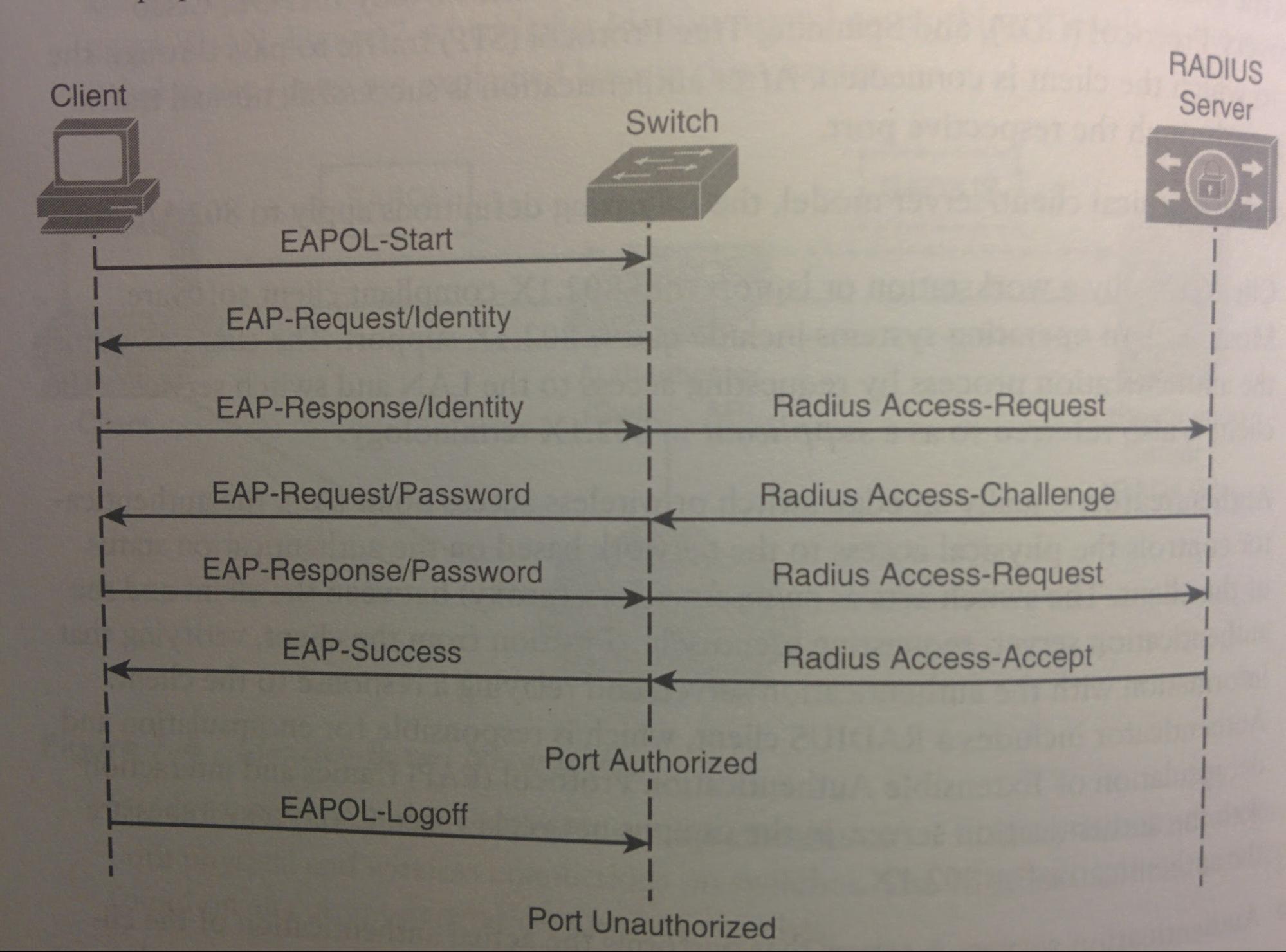
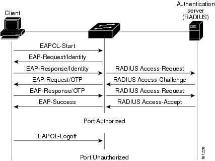
- If pass, the interface is changed to the “authorized state”, the end device’s traffic is no longer restricted, and they are placed into the VLAN assigned to that user (no matter which physical port they are connected to).
- If fail, nothing changes, but the supplicant can retry. (or can be configured to allow guest access with a guest VLAN).
- When the user logs off, or the interface goes down, the interface goes back to the “unauthorized” (un-authenticated?) state.
- Authorization State:
- force-authorized
- (the default) The port is forced to always authorize all connected clients, i.e. everyone is allowed on this int. Don’t do this.
- This is enabled as soon as the global cmd “dot1x system-auth-control” is entered.
- force-unauthorized
- Port will never allow any connected device to be authorized, i.e. nobody is allowed.
- auto
- (the ideal) The port uses 802.1x to test if a end-device is authorized, and if so moves from the unauthorized to the authorized state. This requires an 802.1x-capable application on the client system.
|
S(config)# aaa new-method ! Define the radius server group. See “AAA w/ RADIUS & TACACS+” S(config)# aaa authentication dot1x default group RadiusGroupName ! (see AAA w/ RADIUS & TACACS+) S(config)# dot1x system-auth-control ! enables dot1x globally on this dev (i.e. all access ints. Changing as ints change to/from access mode). S(config)# dot1x host-mode multi-host ! Optional; enables more the ability for more than 1 mac/host to exist on a single port (e.g. a host has a VM, or is using a hub) S(config)# ! S(config)# int g0/1 S(config-if)# switchport mode access ! The int must be in access mode else this others cmds will fail. S(config-if)# dotqx port-control {auto|force-authorized|force-unauthorized} ! enables dot1x on an individual int.
S# show dot1x all |
Network Security
- ASA: “Cisco Adaptive Security Appliance”; Cisco’s line of firewalls.
- MITM: “Man in the middle”; A type of attack where the attacker is logically ‘in the middle’ / in-between two communicating devices.
- DIA: “Dynamic ARP Inspection”; Used to prevent ARP Spoofing (ARP = Address Resolution Protocol)
- Threat sources:
- from the the internet (outside of the network).
- This is where most of today’s security is focused, using edge routers and ASAs, L3/4 header checks, (SPI) stateful packet inspection, etc. This is clear when looking at how ASAs and Rs come from the factory with there ports in a shutdown state.
- from within the network (e.g. rogue employees and contractors, spies, malware on an unsuspecting user’s computer, malfunctioning devices)
- Today’s security focus largely ignores the possibility of an internal threat. This is clear when looking at how S’s come from the factory with their parts all in the ‘no shutdown’ state. (of note, ACI is a new feature for data centers, which does take the secure approach of not allowing coms without explicit instruction.)
- If visitors or contractors are allowed, they could gain physical access to protected resources.
- Notes:
- It is important to have multiple layers of security in case one should be penetrated or fail. I.e. there should be just as much security focus of the internal network because if the security processes preventing an external threat from getting in were to fail, then it is up to the internal security mechanisms to prevent/reduce the damage that can take place.
- Public and hybrid cloud setups, even if secure, can pose new risks. For example attackers from the inside.
- (config)# no service password-recovery ! This makes it so if the password recovery feature is used, it will delete the config and the vlan.dat files. Rumor has it that there is a way around this security feature though.
- Switch Attacks:
- MAC layer attacks
- MAC Address Flooding Attack
- Requirements:
- The number of total (i.e. across all ints) allowed (i.e. not limited by switchport port-security) MAC addresses (i.e. MACs that are allowed to Tx frames on an int) at any given point in time ... is greater than … the number of available L2 MAC address CAM table entries.
- In other words: if any interface is allowed to Tx frames from an absurdly large amount of different MAC addresses.
- How large of an amount classifies as absurdly large? So many that the S can not store all of the source-mac addresses in its MAC address-table.
- In other words: if any interface does not use port-security to limit the maximum source-addresses on an interface.
- Action:
- Flood the switch with frames with unique (typically fake/made up) source MAC addresses, exhausting the L2 MAC address CAM table memory space.
- Effect:
- DoS, typically VLAN-wide; or to collect a broad sample of traffic.
- When the L2 MAC address CAM table memory space is full, it prevents new entries (i.e. MACs) from being added to said table. Thereafter each time the S Rxes a frame which has a source-MAC-address that is not already within the L2 MAC address CAM table (this will occur since the attackers is still flooding the S with uniquely MAC’ed frames, and also occur when other unknown MACs arrive on the S), it will be broadcasted out all ints in the VLAN (possibly traversing multiple trunks). This typically will exhaust the bandwidth of multiple interfaces on multiple switches, causing a DoS attack by utilizing all of an uplink’s bandwidth and thereby denying access to others that use said uplink.
- Mitigation:
- Prevention:
- Configure “port-security max” to limit the total number of useable MACs on a port
- Optionally: Configure “port-security aging” to age out dynamically learned entries after a certain period of time.
- Impact reduction (will reduce, but not eliminate, the impact of this attack):
- VLAN segmentation (minimizing the logical size of VLANs).
- PVLANs (private VLANs).
- ? MAC address VLAN access maps.
- VLAN attacks
- Double-Tagging VLAN Hop Attack:
- Requirements:
- Can occur when a trunk native vlan is the same as the vlan of an access port.
- Action:
- Attacker tags their frame(s) twice ...
- Outer tag being of the vlan that is shared by both their int to the first S (S will accept tagged traffic from an access port if the tag is of the assigned VLAN), and the trunk native vlan between the two switches.
- Inner tag being the vlan that their victim is on.
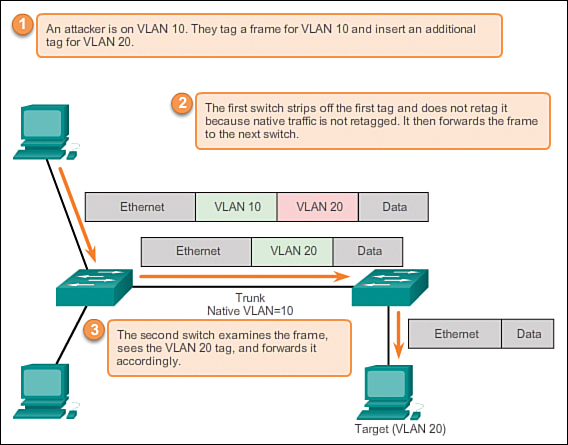
- Effect:
- An attacker gains the ability to Tx (but not Rx) traffic to a device on a different VLAN without the need to pass through a L3 / Distribution-layer device (See Cisco Network Design Hierarchy > Layers) which would typically have more security mechanisms in place.
- Mitigation:
- Prevention:
- Use a separate VLAN for the trunk native VLAN, that is not used for any other purpose.
- Prevent untagged trunk traffic, by doing either (or both) of the following:
- Disallow the trunk native vlan on all potential trunk ints (static, or DTP dynamic).
- Note: this does not impact control-plane traffic. Control-plane traffic will Tx, and will Tx using the native vlan, ignoring the configuration.
- Force 802.1q tagging of all data-plane frames, on each switch.
|
(config)# vlan dot1q tag native ! does NOT strip the tag off of (egress) native vlan traffic, AND drops trunk data-plane ingress untagged traffic. Do this on all ends of trunks. |
- Attacks between devices on a common VLAN:
- Devices in the same VLAN may need protection from one another. (e.g. a service provider with multiple customers)
- Requirements:
- Attacker and target are in the same non-private VLAN.
- Action:
- N/A.
- Effect:
- Attacker has network communication with the target, without the traffic having to traverse a L3 / distribution device (which is where most security is implemented).
- Mitigation:
- Prevention:
- PVLANs (Private VLANs)
- Spoofing attacks
- Switch Spoofing Attack:
- A non-shutdown switchport uses either of the DTP administrative modes, dynamic-auto or dynamic-desirable.
- Action:
- The attacker performs DTP negotiation as if the attacker was a dynamic-desirable switchport and negotiations to form a trunk link.
- Effect: (i.e. This gains the attacker many things)
- For all VLANs that the other S allows on this newly formed trunk link (by default all VLANs), the attacker will be able to communicate on all those VLANs, including Rxing all broadcasts from them. The attacker will be able to communicate will all hosts in the VLAN, possibly without having to traverse to the distribution layer (where more security occurs. See Cisco Network Design Hierarchy > Layers)
- Possibly the ability to manipulate STP, making itself the RS or worse (see STP)
- Possibly more!
- Mitigation:
- Prevention:
- Do not use DTP anywhere, by statically assigning each switchport as either access or trunk.
- Use switchport nonegotiate on all ports.
- Secure all unused ports via: General Setup > Blackhole config.
- Impact reduction:
- For each trunk, only allow the vlans that are known to be required on the trunk int, rather than the default of all vlans.
- DHCP Starvation Attack:
- An attacking device can exhaust the address space available to the DHCP server for a time period.
- Requirements:
- Action:
- Effect:
- Mitigation:
- Use DHCP snooping
- DHCP Spoofing Attack:
- An attacking device can establish itself as a DHCP server in MITM attacks.
- Requirements:
- Action:
- When a host broadcasts a DHCPDISCOVER msgs onto the vlan, it will accept the first response that it receives. The attacker, typically on the same vlan, will act as a DHCP svr and respond. Because the legit DHCP server is typically centralized and the local S will typically act as an IP helper, the attacker is typically able to respond first if it is on the same vlan. The victim will accept the DHCPOFFER and use the attacker as it’s default gateway, and possibly DNS server.
- Effect:
- The attacker is now a MITM between the victim host and the attacker’s default gateway for traffic and DNS requests.
- Mitigation:
- Use DHCP snooping or PVLANs.
- Spanning Tree Compromises:
- Requirements:
- Action:
- Attacking device spoofs the root bridge in the STP topology.
- Effect:
- Attacker gains MITM logical position for multiple types of traffic / frames.
- Mitigation:
- Enable BPDU guard. Alternatively enable Root Guard.
- Proactively configure the primary and backup root devices
- MAC Spoofing:
- Requirements:
- Action:
- Attacking dev spoofs the MAC address of a valid host currently in the CAM table.
- Effect:
- The switch then forwards to the attacking dev any frames that are destined for the valid host add.
- Mitigation:
- Utilize DHCP Snooping.
- Utilize port-security.
- ARP Spoofing:
- Attacker crafts ARP replies intended for valid hosts. The MAC add of the attacker then becomes the destination address that is found in the L2 frames that were sent by the valid network dev, (and intended for the valid host?).
- Requirements:
- Action:
- A device needs to know the MAC for an IP address within its local subnet, so it broadcasts an ARP request, and waits for the reply so to add the MAC-to-IP listing into its ARP cache table for up to 4 hours.
- The attacker replies to the ARP request with an ARP reply listing the attacker’s MAC as the source of the requested IP add. (the reply will typically come after the legit reply, this is because then the victim will overwrite the entry from the legit ARP response with the new entry from the malicious ARP response.)
- Typically an attacker will pretend to be both the victim and the default gateway, so as to become a MITM, where all comms between the real victim and the real default gateway travel through the attacker.
- Effect:
- MITM
- Mitigation:
- Utilize DIA
- Utilize port-security.
- Switch Device Attacks
- CDP Manipulation
- CDP Spoofing/Flooding Attack:
- Requirements:
- Action:
- A user floods (thousands) of forged CDP packets to multicast mac “0100.0CCC.CCCC”.
- Effect:
- DoS; Once a CDP enabled dev Rx’es them, the info is added to it’s CDP table. This resource intensive task of the Rx’er, when multiplied by thousands, can cause a DoS.
- Mitigation:
- Prevention:
- Disable CDP. (Some admins disable CDP because of this, despite its benefits)
- Reduction:
- Disable CDP on ints that do not require it. Such as ints to ISP, end users (that do not use Cisco IP phones), vendors/vendor equipment.
- CDP Data Exposure:
- CDP Tx’s data that may be better kept private.
- Requirements:
- Action:
- Effect:
- Network information is divulged. Including IP addresses, devices models, devices capabilities, interfaces, etc.
- Mitigation:
- Prevention:
- Disable CDP. (Some admins disable CDP because of this, despite its benefits)
- Reduction:
- Disable CDP on ints that do not require it. Such as ints to ISP, end users (that do not use Cisco IP phones), vendors/vendor equipment.
- SSH protocol & Telnet attacks:
- Telnet is sent in plaintext, and therefore is easily susceptible to MITM attacks.
- SSHv1 has security issues.
- Requirements:
- Action:
- MITM attack is performed during a Telnet/SSH session.
- Effect:
- All comms during the session are exposed, including logins.
- (potential for replay attack?)
- (potential for tampering attack?)
- Mitigation:
- Prevention:
- Do not use Telnet or SSHv1. Rather, use the latest version of SSH, currently version 2.
- Unauthorized Rogue Access:
- Connecting rogue networking devs (WAPs, Rs, S’s)
- Because consumer WAPs and Rs are so inexpensive, sometimes users plug these into an organization’s switchports.
- Typically the security settings on these devices are either not enabled or not capable of meeting the security requirements of the organization, which allows others (besides the user) to access the organization’s network without authentication or authorization, and allows others to compromise the device, and/or intercept traffic on said device.
- Deliberate attackers may also connect WAPs or Rs and physically hide them.
- Compromise of a computer.
- Malware on a user’s computer/dev may grant access within the network, even past firewalls at the organization’s network perimeter (because the malware will phone home first, which creates the firewall allow rule).
- Physical
- A user may walk into a wiring closet, or an attacker could sit at a user’s desk with the user’s unlocked computer and boom hacked.
- Security Requirements:
- Passphrases (passwords)
- In all situations, use passphrases of at least 8 characters but ideally more. It is best to use a longer passphrase that can be remembered rather than a passphrase with special characters that is difficult to remember. For example, “CorrectHorseBatteryStaple” is better than “Tr0ub4dor&3”. See xkcd.
- Use external AAA servers rather than individually managing accounts.
- Use “enable secret” rather than “enable password”.
- Use “service password-encryption” to encrypt all passwords that cannot be encrypted using strong authentication. (this uses weak encryption but it is better than plain-text)
- Banners
- Use login banners to warn of legal/employment consequences and monitoring. To configure, see AAA > Configuration section > “BANNERS & PROMPTS” subsection.
- Console
- Secure console access via AAA, or at least some a local username and passphrase.
- VTY lines / Remote access
- Secure VTY line access via AAA, and potentially use ACLs to limit what IPs can attempt login.
- Use the highest version of SSH possible with the largest key size as possible. Never use telnet.
- (config)# ip ssh version 2
- (config)# line vty 0 15
- (config-line)# transport input ssh
- (config-line)# access-class aclName in
- Unused Ports
- Secure all unused ports via: General Setup > Blackhole config.
- Discovery Protocols (CDP)
- Because CDP is transmitted in plain text and without authentication, disable CDP and other discovery protocols on ports that connect to devices outside of one’s control or where not needed (e.g. on ports connecting to ISP, another organization, or to end users that do not use Cisco IP phones).
- Use BPDU guard on all access ports.
- Web server
- Disable the built-in webserver unless it is being used for important things.
- (config)# no ip http server
- (config)# no ip http secure server
- If it must be used, use the HTTPS version, and apply ACLs to it.
- (config)# no ip http server
- (config)# ip http secure server
- (config)# ip http access-class aclName
- SNMP (if using)
- Use only SNMPv3 with Priv, SHA, and AES with the highest possible key sizes.
- Reduce Write view as much as possible, if not entirely.
- Use ACLs to limit SNMPv3 access per group. Optionally also per user.
For DHCP Snooping see DHCP Snooping.
IPSG: IP Source Guard
- PVACL: Per-port per-vlan ACL.
- Used to counter IP spoofing (hijacking the ip address of a different dev).
- Compatibility:
- Compatible only on L2 ints.
- Typically configured on access ints.
- Can be configured on trunks but if the trunk has many VLANs w/ DHCP enabled, the S may not have the hardware to support it.
- Operation:
- DHCP Snooping is a prerequisite, and IPSG only applies to “DHCP-Snooping Untrusted” ints.
- When enabled, initially the S blocks all ip traffic except those that are picked up by DHCP snooping.
- Once a dev has either received a DHCP address (captured by DHCP snooping) or the host manually configures a static IP address, that IP address is bound to that port, the initial traffic restriction is removed and the PVACL is applied.
- The PVACL will then only allow ingress packets on that port that have the same source IP address that was binded to that port initially (the ip address configured statically or Rx'd via DHCP), all other ingress packets (packets with a different source-ip add) are filtered/dropped. This prevents IP spoofing.
- Filters:
- There are two different filters that IPSG can use (both can be used at the same time).
- IP source filter (the default):
- Ingress traffic is checked to verify same source-IP address as is bound to that int.
- IP MAC source filter:
- Ingress traffic is checked to verify same source-IP address as is bound to that int, and that the same source-mac as is bound to that int/ip add.
- if the IP filter is enabled without any IP source binding on the int, the default PVLAN is applied to the int, which denies all traffic.
- maintains PVACLs, based on IP-to-mac-to-switchport bindings.
|
S(config-if)# ip verify source S(config-if)# ip verify source port-security
S# show ip verify source |
! (required) Enables IPSG on the int. ! (optional) after doing the above cmd, this cmd will cause the S to also verify the MAC.
! Verification |
DAI: Dynamic ARP Inspection
https://www.cisco.com/c/en/us/td/docs/switches/lan/catalyst6500/ios/12-2SX/configuration/guide/book/dynarp.html
- Purpose:
- Prevent ARP spoofing and ARP poisoning.
- Operation:
- Requires DHCP snooping is enabled first.
- Filters-out invalid and gratuitous ARP replies within the VLAN.
- Intercepts and inspects all ARPs (requests and replies) on untrusted ports. Then, similar to IPSG, checks if the ARP’s MAC-to-IP binding is correct by checking it against the DHCP Snooping MAC-to-IP table. DAI also checks against “user-configured ARP ACLs” (for hosts that statically configure their IP add).
- DAI can also be configured to err-disable an untrusted int if ARP traffic exceeds a configurable threshold. Or it can be configured to drop, log, or drop and log, arps that do not match.
|
Once DHCP Snooping has been configured…
S(config)# ip arp inspection vlan 1,9,80,666-667
S(config-if)# ip arp inspection trust
S# show ip arp inspection [log | ...] |
! Enables DAI on vlans 1,9,80, & 666 through 667. Typically mimics the vlans used in the cmd “ip dhcp snooping vlan ...”.
! Typically done on the ints that also have “ip dhcp snooping trust”. By default all ints are untrusted, this cmd makes them trusted.
! Verification |
Port-Security
- Inabilities:
- Port-security can not be used on SPAN destination ports or on port-channel ints.
- Adding ‘secure’ (trusted) MACs:
- This effectively populates the L2 MAC address CAM table with entries. Each individual secure mac can exist on only 1 interface at a time (this prevents the mac from operating on any other int on that S).
- Secure MACs are the source MACs that this interface will allow to be Rx'd on this int. In other words, when this int Rx’s a frame, it checks if the source-mac add of the frame is a secure MAC.
- if the source-mac is a secure MAC, the frame will be processed as normal.
- If the source-mac is not a secure MAC …
- … and the port-security max (discussed below) has not been reached:
- The source-mac will be “dynamically-learned” by adding it to as a secure-mac, and the frame will then be processed as normal.
- … and the port-security max (discussed below) has been reached:
- The frame will be dropped and the ‘violation action’ (discussed below) will occur.
- How a Secure-MAC is defined:
- Statically:
- Manually add secure MAC addresses via the “switchport port-security mac-address …” interface sub-cmd.
- These MACs are added to the running-config (make sure to do “copy run start” to save these to the startup-config), and therefore is not subject to the port-security ‘aging timer’ (discussed below).
- These MACs are then only allowed on that int (possibly able to connect on a diff vlan?), and will cause a port-security violation if connected to a different one.
- Dynamically:
- Secure MACs will be learned by the next source address that Txs from this int.
- In other words, the next device on the int will have it’s MAC add temporarily (i.e. not to the running-config) added as a ‘secure’ MAC.
- As soon as the int goes down (e.g. user turns their comp off, or the attacker disconnects) the S will remove all dynamically-learned L2 MAC address CAM table entries for that int (not the sticky or statics).
- Max:
- Sets the maximum (1 - 4097) total (static and dynamic combined) number of secure MACs on the int. (default is 1).
- Once reached, no additional secure macs may be defined until others are removed (either manually removed or aged out). Additionally when a non-secure mac attempts to Tx from this int, it will be dropped and the security violation action (discussed below) will be invoked.
- Aging Timer:
- By default, there is not aging timer, and MACs are never automatically removed.
- When enabled, the timer (defined as any whole number between 1 - 1440 minutes) expires, the interface will remove the dynamically-learned (i.e. non-sticky / non-static) secure MAC add from the L2 MAC address CAM table.
- Sticky:
- Sticky can be used without the MAC address parameter, which enables all future dynamically-learned MACs (unless the max secure adds have already been defined) to become “sticky” which converts them from dynamically learned addresses to statically learned addresses (and adds them to the running-config).
- Converts dynamically-learned secure MACs on this int, into statically configured “sticky secure” MACs on this int (and adds them to the running config as if they were statically configured thus they are no longer subject to the port-security aging timer). “Sticky secure” prevents MAC(s) from moving to a different int, (and from being automatically removed by the aging timer ?).
- Violation action (in order of severity):
- Shutdown:
- (the default) Places the port into the “err-disable” state (error-disable),
- Err-disable state: Essentially shuts the port down. One can “shut” ”no shut” the int to turn it back on, however if the issue that caused the err-disable is still present then it will err-disable again.
- Causes:
- Port-security violation, duplex mismatches, excessive link flapping, UDLD violation, STP Root/BPDU Guard violation, PortChannel misconfiguration, other (late collision detection, L2 tunneling protocol guard, DHCP snooping rate-limit, incorrect gigabit int convert (Gigastack GBIC), or ARP inspection.
- The “errdisable detect cause” cmd is used to configure these and additional reasons to errdisable an int. All above reasons are the default reasons.
- Auto-recovery
- https://www.cisco.com/c/en/us/support/docs/lan-switching/spanning-tree-protocol/69980-errdisable-recovery.html#anc6
- This feature will shut/no shut the int after a configurable amount of time to attempt to restore functionality. This work if the original issue has been removed, else it just makes more logs.
- This feature is not enabled by default.
- Restrict:
- Drops traffic from insecure MACs, continues to allow traffic from secure MACs, increments the security-violation counter by 1.
- Can be configured to Tx an SNMP trap msg, and a Syslog msg when a violation occurs.
- Protect:
- Drops traffic from insecure MACs, continues to allow traffic from secure MACs, does not increment the security-violation counter.
|
(config-if)# switchport port-security ! enables port security on the int. (config-if)# switchport port-security aging time mins ! after mins removes the secure mac address. (config-if)# switchport port-security aging type {absolute | inactivity} ! sets if time is absolute / since creation (the default), or inactivity / last used. (config-if)# switchport port-security max max [ vlan vlan|vlan-list ] ! limits the max number of active (i.e. non aged-out) MACs allowed to Tx from this int. If int is trunk, this cmd allows the use of the [vlan] parameter. (config-if)# switchport port-security mac-address [sticky] [mac] [vlan {vlan|voice}] ! Define what mac address(es) are allowed on the port. (config-if)# switchport port-security violation {shutdown | restrict | protect} (config-if)# switchport port-security limit rate invalid-source-mac [100] ! Sets the limit for bad packets. In this example 100 units is used. (config)# errdisable detect cause [all | causeName] (config)# errdisable recovery cause [causeName | all] ! e.g. psecure-violation (config)# errdisable recovery interval seconds ! defaults to 300 seconds.
# show int status err-disabled ! brief list of err-disabled ints and reason. # show port-security [int int] ! Both with and without the parameter are very helpful. With int parameter, lists a ton of port-security info for an int. # clear port-security {all|configured|dynamic|sticky} [address mac | int int] ! clears specific entries from the L2 MAC address CAM table. Typically to then allow a known legit MAC on. # show errdisable recovery |
Storm-Control
- Causes for storms:
- Network misconfigurations (e.g. STP misconfig)
- Host misconfigurations
- DoS attacks
- or more.
- Definition:
- A S runs a process called “traffic storm-control” (aka “traffic suppression”) to monitor, in 1 second intervals, the traffic on an int and limit the impact of traffic storms.
- Operation:
- Best if, before implementing storm-control, the existing network is monitored over a long period of time (with a tool such as iperf) to set a baseline for how much traffic is normally used. Then use this to set appropriate storm-control thresholds.
- Typically configured on access ports that connect to hosts (to prevent that traffic from traversing more ints), but can also be done on trunks.
- Types of traffic storm-control can monitor:
- Broadcast
- Multicast (Note: some Cisco S’es consider multicast traffic as broadcast traffic.)
- Unicast ( Unicast in this sense means ‘unknown unicast’ frames, and therefore does not apply to regular unicast traffic)
- Threshold Types
- Rising/Upper Threshold: What level to begin blocking type of traffic.
- Falling/Lower Threshold: What level to stop blocking the type of traffic. (if omitted, then the falling threshold level is implicitly set to the rising threshold level)
- Threshold Metrics: Both thresholds (rising & falling) are in one of the 3 following metric:
- Bits per second (bps) (can use ‘k’, ‘m’, and ‘g’ to indicate kilobits, megabits, gigabits. e.g. “1g”)
- Packets per second (pps)
- Link bandwidth utilization percentage, per second (Note: some IOS images will round to the nearest 0.33%)
- Actions when a Threshold is exceeded:
- When the rising threshold for a certain type of traffic is exceeded, the switch will block that type of traffic until it is reduced to below the falling threshold.
- Additional Actions: (either or both of the following can also be done when ANY of the rising thresholds are exceeded.
- Additionally the S can also err-disable (“shutdown”) the entire int.
- Additionally the S can also Tx an SNMP trap.
|
(config-if)# storm-control [Broadcast|Multicast|Unicast] level {Rising%|Bps risingBps|Pps risingPps} [falling%|Bps fallingBps|Pps fallingPps] ! Set thresholds for 1 type of traffic. (config-if)# storm-control [Broadcast|Multicast|Unicast] level {Rising%|Bps risingBps|Pps risingPps} [falling%|Bps fallingBps|Pps fallingPps] ! Set thresholds for another type of traffic. (config-if)# storm-control action {shutdown | trap} ! Set additional actions to take when any of the int’s rising thresholds are exceeded. # show storm-control [Broadcast|Multicast|Unicast] ! if no additional parameters are used, only returns for broadcast stuff. filter state={blocking||forwarding}. |
SDN: Software Defined Networking
- SDN Controller:
- “Software Defined Networking Controller”. Centralized controller software. In 2010s, move from “distributed control plane” (running on each dev and communicating via datagrams such as BPDUs or OSPF LSAs amongst one another) to many control plane functions being moved to a centralized SDN controller (software). May control all of Control plane function, or just observe (i.e. control none of the control plane functions). Can exist anywhere on the network that has IP connectivity. Typically depicted above the devices that it controls in network diagrams. Things that SDN Controller may gather: all devs in net, their abilities, ints, int states, what each int connects to (topology), configs (ip addresses, VLANs, etc.)
- Planes (Management, Control, & Data): See Planes.
- ASICs, CAM & TCAM: See Types of Memory.
- “Interfaces”:
- As used in SBI, NBI, & API, is software interface. In contrast to everywhere else in networking which uses the term interface to refer to hardware.
- Southbound Interface (SBI):
- Because SDN Controller is typically depicted above the devices that it controls, the (software-) interface between the two is called the SBI, or the Southbound interface. Because from the SDN controller, the interface is “southbound”. A (software-) interface between the SDN controller and the networking device. There are many different SBIs. Goal is network programmability, for the SDN program/controller to control the control plane of the networking device. Some include a protocol (so the SDN controller and devs can communicate), but often they include an API (application programming interface). Examples: OpenFlow (from the ONF https://openNetworking.org), OpFlex (from Cisco; used with ACI), & “CLI (SSH) and SNMP (from Cisco; used with APIC-EM)”.
- Application Programming Interface (API):
- Method for one application/program to communicate (possibly across the network) with another. Often exists as usable code (functions, variables, data structures), in comparison to a protocol which is just a document (often) from a standards body.
- Northbound Interface (NBI):
- The NBI is an API that allows a program to communicate with the SDN controller. (e.g. a Java API)
- Application vs Program:
- Program = a set of instructions that can be executed on a computer.
- An application is a program that directly helps a user perform tasks (has a GUI).
- SDN Application:
- An Application that is depicted above the SDN controller and the NBI in network diagrams. The app may be on the same server/device that the SDN controller is, or it may be on a different server/device and use REST APIs (see REST APIs). The application uses the NBI to communicate with the SDN controller. Uses it to access the SDN controller’s data, functions, and ability to program flows into the devices (via SBIs), all using the controller’s NBI (e.g. a Java API). Anyone can make their own Application to perform this task, it must be compatible with the same OS that the SDN controller is on and be compatible with the NBI (e.g. a Java API). It takes in information from the SDN controller and inputs flows to the devices though the SDN controller (ask the controller to add specific match/action logic (flows) into the forwarding tables of the devices).
- REST APIs (as such for a controller):
- REpresentational State Transfer. A type of API that uses HTTP messages to communicate between the application on one device and the SDN controller on another device. (not used when they are on the same device). The application will use HTTP GET requests for a particular URI (like those used to retrieve web-pages). The URI specifies an object on the controller (typically a data structure that the application needs to learn and then process. e.g. an object that is a list of physical ints on a specific dev along with the status of each). The SDN controller responds with an “HTTP GET Response” containing the object (variable names and their values), typically in the format of JSON (JavaScript Object Notation) or XML (eXtensible Markup Language).
- Open SDN Controller and OpenFlow:
- An example of SDN and network programmability solution. Made by the Open Networking Foundation (https://www.OpenNetworking.org), a consortium of users and vendors for establishing SDN (Controller, SBI, NBI, protocols, anything) in the marketplace. SBI is OpenFlow, part of which defines IP-based protocol used to communicate between SDN controller and devices. OpenFlow (the SBI) defines a standard idea of what a switch’s capabilities are based on the ASICs and TCAMs used in switches today (This is called a “switch abstraction”). Switch can act as L2S, L3S, or other. OpenSDN model centralizes most of the control plane in the SDN controller and SDN application (much centralization, rather than the networking devices themselves). Calling for OpenFlow as the SBI, and switches that support the OpenFlow SDI. Two possible controllers are the “OpenDaylight SDN Controller”, and the “Cisco Open SDN Controller.”
- OpenDaylight SDN Controller (ODL):
- A project of the Linux foundation (woot woot) with backing from many vendors including Cisco. Many organizations came together to work on it together. Can use many different SBIs (not just OpenFlow). Many other SDN controllers are based off this, including Cisco Open SDN Controller. Many features.
- Cisco Open SDN Controller (OSC):
- Cisco’s commercial version of, and based off of, ODL. Works on some Cisco Nexus (data center level) switches, and some Cisco ASR routers (supporting OpenFlow).
- Cisco Application Centric Infrastructure (ACI) and OpFlex:
- An example of SDN and network programmability solution. Controller = “Application Policy Infrastructure Controller (APIC) (not the same as APIC-EM). Uses concepts of “endpoints” (VMs that can move) and “policies”. Many endpoints share the same needs, so you group them into “endpoint groups”. Policies are applied to these endpoint groups, defining such things as which VM can talk to which, QoS parameters, etc. Then the Cisco Application Centric Infrastructure program programs that information into the networking devices. Using a centralized SDN controller called the “Application Policy Infrastructure Controller (APIC) (has a GUI), the controller that creates application policies for the data center infrastructure. Partially centralized control plane, RESTful and native APIs, and OpFlex as an SBI. Control plane is mixed between the ACI controller and the switches (they must support ACI; not your normal switches).
- Cisco APIC Enterprise Module (APIC-EM):
- An example of SDN and network programmability solution. Works on regular switches, the switches do not need to be specifically made for APIC-EM. Not the same as APIC (very different). Centralized, “APIC-EM”, SDN controller. Cisco provides many applications that reside on the SDN controller. RESTful NBI. To support current networking devices, the control & data planes remain unchanged (to support more devices). SBI uses SSH & SNMP. Enables easier network automation, by gathering info (over SBI), makes it available via many different NBIs. Can configure the devices via SNMP (set cmds) or SSH.
|
Criteria |
OPEN SDN |
ACI |
APIC Enterprise |
|
Changes dev control plane |
Yes |
Yes |
No |
|
Centralized point for automation / control |
Yes |
Yes |
Yes |
|
Degree to which control plane is centralized |
Mostly |
Partially |
Not at all |
|
SBIs used |
OpenFlow |
OpFlex |
SSH + SNMP |
|
Controller mentioned |
OpenDaylight, Cisco OSC |
APIC |
APIC-EM |
|
Main Organization behind it |
ONF |
Cisco |
Cisco |
- Cisco APIC-EM Path Trace ACL Analysis Application: APIC-EM has the core, but also includes base apps (free/non-paid), in contrast “solution apps” require the purchase of a license to legally use. The “APID-EM Path Trace App” predicts data plane actions. First APIC-EM application called “Discovery” discovers the net topology, then user inputs L3 source and destination info into Path Trace tool’s GUI, the application analyzes routing and forwarding tables etc to determine where this packet would go to reach dest, then displays this on a topology maps with notes and the route. ACL analysis tool does same but takes into account ACLs.
Cloud Computing
- vCPU:
- A virtual CPU, used by a VM.
- vSwitch:
- A “virtual” switch. A software switch. (like a VM). Can use the vSwitch provided by hypervisor, or 3rd party (e.g. Cisco). Switchport config follows VM as hypervisor moves it across servers (while VM running).
- Nexus Switch:
- Cisco’s vSwitch line. (e.g. “Nexus 1000v”, v for virtual.)
- NX-OS:
- OS on Cisco Nexus vSwitchs.
- Certs:
- Cisco CCNA,CCNP,CCIE Data Center certs cover these.
- VM:
- Each VM can be in its own VLAN, share a VLAN, or even use VLAN trunking to the VM.
- ToR Switch:
- “Top of Rack” switch. Usually 2+ switches, where each switch has 1 (or more) connections to each server that is below it (for redundancy). These are Access-layer switches.
- EoR Switch:
- “End of Row” Switch. All ‘ToR Switches’ (access-layer switches) connect to EoR Switches (distribution-layer switches). Typically in a separate (end) rack to the side of all the other racks in DC.
- Cloud Computer: Requirements...
- On-demand self-service: Requires self-service (automated, not a human spinning the VM up).
- Broad network access: Must be available from many types of devices and over many types of networks (e.g. the internet)
- Resource pooling: (Virtualization) Creates a pool of resources to be used by different VMs, not one specific VM.
- Rapid elasticity: From the customer’s end, must be able to purchase new (seemingly unlimited) resources quickly with minimal delay.
- Measured Service: Provider can measure usage and report to client for transparency and billing.
- Private Cloud:
- Used for internal purposes to an organization, within the same org.
- Public Cloud:
- Cloud service providers and not part of the same organization as the client. (Like a WAN SP renting out a WAN connection, but a Cloud SP renting out a VM). Typically offer connection the the SP cloud via internet VPN or private WAN. (e.g. AWS)
- Service Models: Rather than purchasing a thing, Cloud is offered as a service.
- IaaS:
- “Infrastructure as a Service”. VM+sometimesOS ; Client purchases virtual hardware (a VM), and optionally an OS. SP provides the client with information on how to connect to the VM.
- PaaA:
- “Platform as a Service”. VM+OS+IDE ; (commonly used for development), comes with many more software tools (IDE) beyond the basic OS of IaaS. (e.g. Google’s APp Engine Paas, Eclipse ISE, Jenkins.io)
- SaaS:
- “Software as a Service”. VM+OS+Software ; Client purchases a VM running a specific software (as a service. E.g. email server), and the SP is responsible for setup and maintaining it. The client does not setup anything. (e.g. ProtonMail, Office 365, iCloud, Google Drive, Dropbox)
- Connections to Cloud:
- Internet:
- Pros:
- Pre-existing internet connection, can migrate between public cloud providers easily, minimal setup time, users can be distributed anywhere that has internet (home, work, library, etc)
- Cons:
- Less secure than private WAN (greater change for MITM), increased internet connection bandwidth needed, no QoS/SLA guarantee ( increased jitter, delay and packet loss compared to private WAN. No Guarantee that connection won’t go down.
- Internet with VPN:
- may have a organizations router actually on the cloud provider’s premises.
- WAN
- Intercloud Exchange:
- WAN connection to intercloud exchange, and
IOS Upgrade
- Get the new IOS file (typically a .bin file) to a tftp server. For this example we’ll put it on another router and make that router act as a tftp server.
- Note: Some cmds require the “/” symbol when specifying file locations (e.g. boot system cmds), while others require it not be used (e.g. verify cmds).
- FS:
- “File System”; this is typically “flash” but simply depends on the device, and if any external storage is added to the device. To list all FS’s use “show file system”.
|
tftp-router(config)# ip tftp source-interface Loopback0 ! Required on some devs like 4331s. tftp-router(config)# tftp-server FS:file-name [alias shorterName] ! Makes dev a tftp server, serving file-name, but it will also accept requests for shorterName as an alias for file-name.
R# show version ! Record what OS this device is currently running. ! Verify enough flash for new OS during runtime via line “#K bytes of processor board System flash (Read ONLY)”. ! Verify enough RAM/DRAM for new OS during runtime via line “... with #K/#K bytes of memory.”. If 2 numbers like this, it is DRAM, combine the two for total DRAM.
R# show file systems ! use this to verify you have drive space to hold the new OS or ideally both the current and the new OS. Verify if flash: or bootflash: or other location. R# dir ! check what the first file is. When dev boots, it will attempt to load all OS’s listed in boot marker list(in nvram:/startup-config), and if none or unsuccessful, will attempt to boot to the first file in the default dir location (usually this is flash:). R# copy tftp: FS: ! here we copy from a tftp server to flash:, it will prompt then for the tftp server ip, the name (or alias) of the tftp server’s file to copy, and then the name to write it as. ! each “!” will represent 10 successful packets transmitted, while “O” mean something else ??? this will take a while (an hour or two maybe). The transfer continues even if the session times-out. R# verify [/md5] FS:fileName expectedHash ! verifies if what the dev has is the same as what it should. calculates the hash of the file and compares to expectedHash. R(config)# no boot system ! removes all previously stated OS’s to boot to (not the files just the listing that says to boot to it) R(config)# boot system FS:/fileName ! make an entry (sequentially) telling dev to attempt to boot to this device in the order of the “boot system flash” cmds. R(config)# boot system FS:/fileName ! Tries this entry next if ^ fails. etc etc. R# show run | b boot-start-marker ! find in running-config which os’s to attempt to load. R# copy flash:/running-config nvram:/startup-config R# reload [in 5] reason IOS-UPGRADE ! reload in a certain amount of time. |
For Install mode see: https://www.cisco.com/c/en/us/td/docs/switches/lan/catalyst3850/software/release/16-3/release_notes/ol-16-3-3850.html#72234
Wireshark
Wireshark filters:
tcp.connection.syn
#right click, follow tcp stream
ip.addr==192.168.1.10
#only packets to/from that address
TO BE ORGANIZED
NM = Cisco Network Module
write erase= erases nvram (non volatile memory) this will erase any configuration
clear start (startup config)= ^
show startup-config= show backup of current config
if responds "startup-config is not present" means it has been erased or has never been made
reload = restart
__________________________
vty=virtual terminal
netstat -an
TCP states:
ESTABLISHED - SYN, SYN-ACK, ACK. / 3way handshake completed
LISTENING - waiting for SYN
TIME_WAIT - waiting for FIN-ACK ACK FIN-ACK ACK. Just going to sit here, eventually will time-out
UDP has no states
netstat -an | find "ESTABLISHED"
_________________________________
end
#sends you back to non-enabled mode
Cable: uses the coaxial cable from TV lines (cable modem) shared BW
DSL: uses the copper PSTN lines (always on) dedicated
Dial-up: uses copper PSTN lines, but consumes line (can't use while on call
UDP header = Source+Des port, length, checksum
Serial DTE or DCE? "show controller serial0/0/0"
Suspend terminal session? "Ctrl+Shift+6 +X"
Resume? "where"
"resume [connection]"
"resume" will resume the last connection
"2" will resume connection 2
"where" will list the connections
MTU: Maximum Txion Unit
normal : 1500 B
babyGiant: >= 1600 B
jumboFrame >=9216 B
system mtu BYTES
system mtu jumbo BYTES (only on Gig)
<Multi-cast IP/MAC addresses>
0100.5E27.0C01
<Multi-cast IP/MAC addresses>
multicast IPs start with 224-239
First 24 bits of multicast MAC: 0100.5E
25th bit always 0/0
remaining 23 bits created from last 23 bits of the multicast IP add.
0000 0001 0000 0000
0101 1110 0|010 0111
0000 1100 0000 0001
x.39.12.1
</Multi-cast IP/MAC addresses>
_____________
which syslog msg type only accessible to admin on cli? debugging
# show ip cache flow
shows which protocols (L4) use most traffic
when sending packet...
each device will replace "source MAC add" with it's own.
IP add will stay same though.
destination MAC = next hop's mac
"show protocols" =
show IP adds on each int
show layer1 & layer2 status of each each int
"show int" =
see MACs on
--------
>restart int (that has been violated, by port security)
(config-if)# shutdown
(config-if)# no shutdown
>reset int
(config)# default int [int name]
>set L2 MAC add
(config-if)# mac-address 0200.0000.0011
# show int [int name]
# show int trunk
# show vlan [brief]
# show port-security int [int #]
# show vlan id <vlan ID>
# show run int <int>
# show port-security int [int #]
# show port-security
# show mac address-table
# show mac address-table dynamic
# show inventory
# show env fan
# show env power
# show env temperature
# show users ! show sessions
# clear line <number listed in ‘show users’> ! this ends a session
Working on an HP (ProVision, Comware, 3Com) switch? Check out https://h17007.www1.hpe.com/docs/interoperability/Cisco/HP-Networking-and-Cisco-CLI-Reference-Guide_June_10_WW_Eng_ltr.pdf
# show tech-support
# show environment ! this includes much information including power temp and fans